
The OpenMANET radio carries the data, but the thing you actually look at is the phone running ATAK. I’ve got a few Galaxy S9s set aside as the end-user devices (EUDs), and poking a touchscreen with gloves on while it’s strapped to your chest gets old fast. So there’s a side build going: an ATAK button case with real buttons you can find by feel. Here’s a first look before the full write-up.
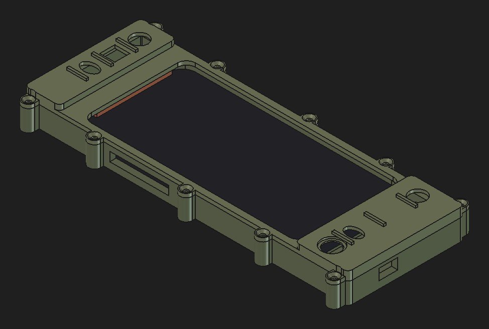
v4: one-piece body, screw-down lid, and three buttons per side with different hole shapes so you can find them by feel.
The idea
- Landscape, on the chest. The phone rides screen-up in landscape with a raised “wing” at each end.
- Three buttons per wing. Each hole is a different shape (round, square, oval, counterbored), so you know which one you’re on without looking down.
- The phone plugs into the case. This idea comes from my RAM Mount GDS tablet cases. The S9 slides onto a USB-C plug inside the case, and charging and data come in through ports on the outside. Nothing dangles off the phone itself.
- The buttons are just a keyboard. A small controller in the case shows up to the phone as a USB keyboard, so each button sends a keystroke. Mapping those keystrokes to ATAK functions (drop a marker, center on me, and so on) comes later.
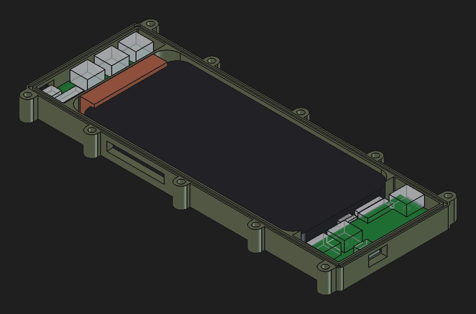
Lid off: the hub board in one wing, the button board in the other, and the drop-in wedge holding the phone onto its USB-C plug.
Two custom boards
All of the electronics live on two boards I designed in KiCad. Both are finished, pass every design check, and are sitting in a folder ready to order from JLCPCB.
- Hub board (right wing): the USB hub, the button controller, power for the phone, a data port out to the radio, and three buttons. It’s a 6-layer board only 0.8 mm thick. The USB-C plug that goes into the phone straddles the board edge with pins on both faces, and that one part only fits a 0.8 mm board.
- Button board (left wing): three more buttons and the USB-C charge port. A 14-wire cable runs under the phone to tie the two together.
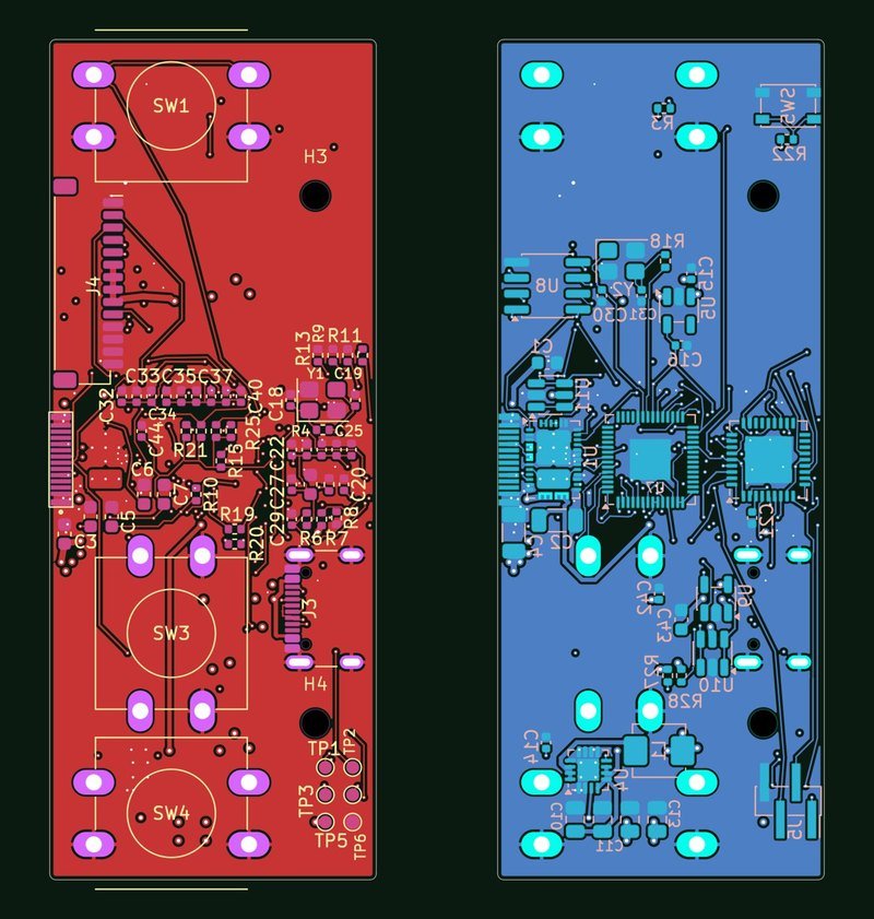
The hub board, top and bottom: a 6-layer, 0.8 mm board that plugs straight into the phone.
Where the print is
v3 got printed and strapped on. The overall shape and size sit well on the chest, so that stays. But the separate left-end piece felt fragile, and the slots for the phone’s own side buttons were a little off. So v4 changes how it goes together:
- One-piece body with a screw-down front lid. Ten M3 cap screws into heat-set inserts, all outside the seal.
- An o-ring cord seal around the lid joint. The ports and screen still need plugs and a film before I’d call it splash resistant.
- A drop-in wedge that holds the phone onto its USB-C plug. The phone drops in, slides onto the plug, the wedge goes in behind it, and the lid goes on.
- A bolt-on mount pod with the AMPS hole pattern, so the mount can be swapped.
- The phone’s side-button slots moved to match the test print.
It grew a bit for all that: about 215 × 78 mm, roughly 30 mm thick with the pod. v4 is printing tonight on two printers at once, so I’ll have a usable one in hand either way.
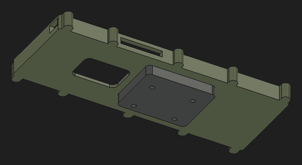
Back side: a bolt-on pod with the AMPS hole pattern for the chest mount.
Coming up
- How v4 prints and fits.
- Ordering the boards, then the full build write-up with all the details.
- Soft TPU button caps captured in the rigid print. That’s my own R&D project once the boards are in hand.
- Mapping the buttons to ATAK functions.
This is a side build of the OpenMANET radio project. The latest radio work is in part 7: 5 GHz on the mesh.