
Two bench nodes with antennas flopping around on pigtails and a GPS puck sliding across the desk got old fast. So I made a quick Raspberry Pi 4 test stand to wrangle the mess until this stack moves into a real radio body. It printed once, fit the first time, and both nodes live on one now. Files are free at the bottom.
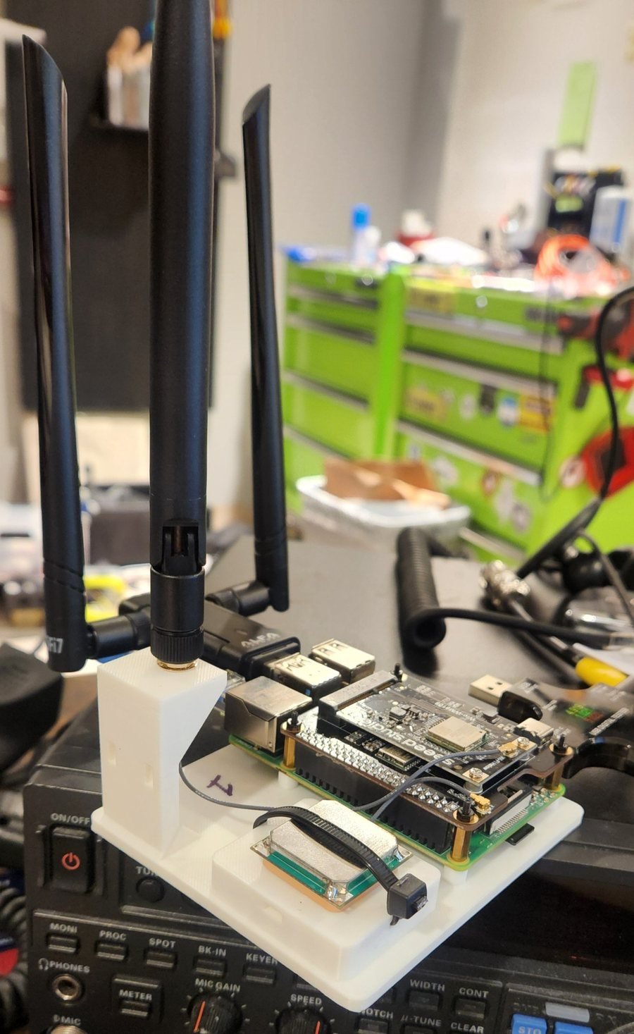
The real thing: node 1 on its stand, with the HaLow HAT, the 915 MHz antenna up on the tower, the GPS zip-tied down and the Alfa 5 GHz adapter plugged in.
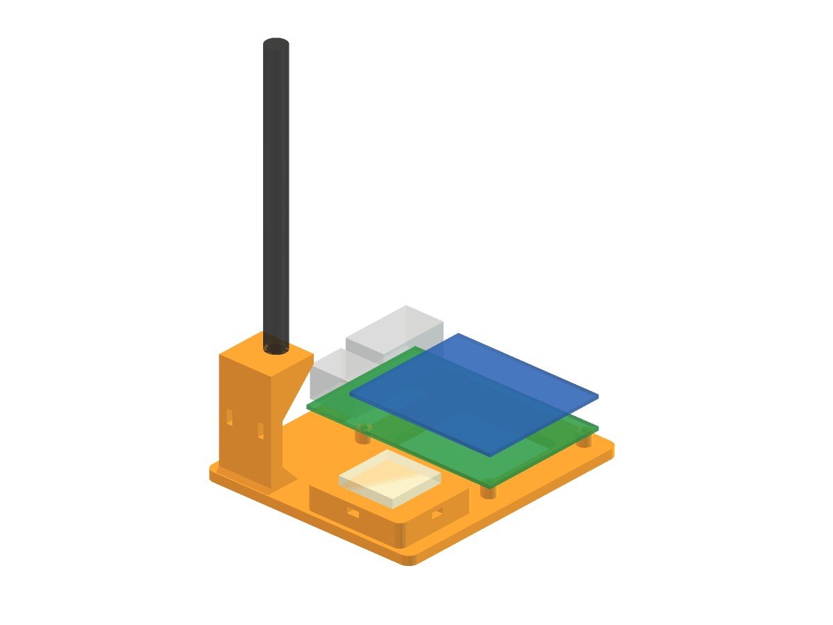
The stand with the node in place. The Pi, HAT, GPS patch and antenna are see-through reference parts.
What the Raspberry Pi 4 test stand holds
- The Pi 4 and HAT on four 5 mm posts. All the Pi’s ports hang off the edges, so power, HDMI, USB, Ethernet and the SD card all stay reachable. Vent windows sit under the board.
- The 915 MHz antenna, upright. A tower behind the stack has a shelf at 50 mm with a 6.6 mm hole. The SMA bulkhead goes up through it and the antenna screws on top, clear of the HAT.
- The GPS antenna on a 44 × 38 mm pad with two crossed zip-tie tunnels just under the surface, so you can strap it either direction.
- The u.FL pigtail ties off through two slots in the tower wall, so nothing pulls on the tiny connector.
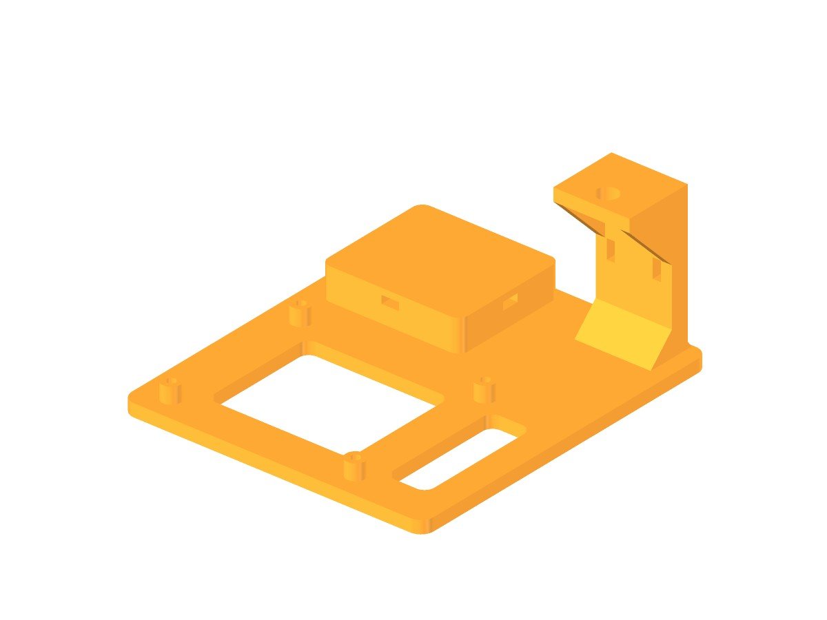
The bare stand: four posts for the Pi, vent windows under the board, the GPS pad and the antenna tower.
Printing it
- Prints flat on the bed, no supports. The shelf gussets are 45° and the shelf underside bridges about 18 mm.
- About 57 cm³ of filament. Any material works; it’s a bench fixture.
- Base is 95 × 108 × 4 mm. Print one per node.
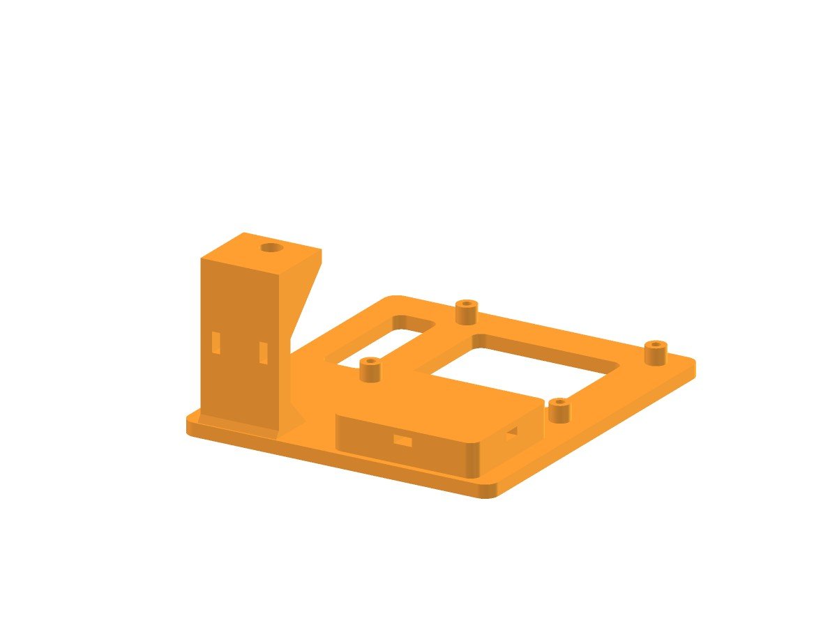
Antenna tower: SMA bulkhead hole up top, zip-tie slots for the pigtail, and the GPS pad’s tie tunnel.
Hardware and assembly
- Swap the four short screws under the Pi for M2.5 × 12 mm screws. They go up through the recessed holes in the bottom of the stand, through the Pi, and thread into the HAT’s brass standoffs.
- Push the SMA bulkhead up through the shelf hole and put the nut on from above. Screw the antenna on.
- Zip-tie the u.FL pigtail through the tower slots.
- Set the GPS antenna on the pad and run a zip tie (up to about 4.8 mm wide) through either tunnel.

Underside: recessed holes for the four M2.5 × 12 screws, plus the vent windows.
Fit notes
The 6.6 mm SMA hole (1/4-36 thread) was the one dimension I couldn’t confirm before printing. It fit my connectors on the first try, and so did the screw holes. If yours is tight or sloppy, the FreeCAD macro in the download has an SMA_D parameter at the top. Change it, run the macro, and it spits out a new STL.
Download the Raspberry Pi 4 test stand
The zip has the printable STL, the FreeCAD model (with the reference parts), the FreeCAD macro that rebuilds it from parameters, and a short README with these notes.
Download the test stand files (.zip, 121 KB)
It’s built around the Seeed WM1302 HAT and the stock OpenMANET phase 1 parts from part 3, but it’ll hold any Pi 4 with a HAT, an SMA antenna and a puck GPS.
The OpenMANET build log
- Part 1: What OpenMANET is (and why I’m building one)
- Part 2: The dual-band, CM4 and handheld plan
- Part 3: Phase 1 parts list
- Part 4: Two-node mesh up, push-to-talk working
- Part 5: The handheld, rendered
- Part 6: A printable Pi 4 test stand (you are here)
- Part 7: 5 GHz on the mesh
—
TL;DR: A no-supports Raspberry Pi 4 test stand for OpenMANET bench nodes: Pi and HAT on posts, 915 MHz antenna upright on a tower, GPS zip-tied to a pad, pigtail tied off. Four M2.5 × 12 screws and a few zip ties. Free STL and FreeCAD files above.
Pingback: OpenMANET Dual-Band Plan: HaLow + 5 GHz, CM4 and a Handheld | Signals & StaticSignals & Static
Pingback: OpenMANET 5 GHz: Dual-Band Mesh Results, Breakage and What's Left | Signals & StaticSignals & Static