Teaser: An ATAK Button Case for My Galaxy S9 EUDs

The OpenMANET radio carries the data, but the thing you actually look at is the phone running ATAK. I’ve got a few Galaxy S9s set aside as the end-user devices (EUDs), and poking a touchscreen with gloves on while it’s strapped to your chest gets old fast. So there’s a side build going: an ATAK button case with real buttons you can find by feel. Here’s a first look before the full write-up.
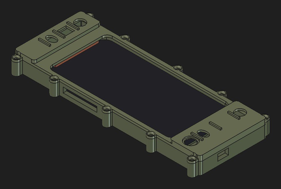
Render of the v4 ATAK button case for a Galaxy S9: one-piece body, screw-down front lid, full-width screen window and three shaped buttons on each end

v4: one-piece body, screw-down lid, and three buttons per side with different hole shapes so you can find them by feel.

The idea

  • Landscape, on the chest. The phone rides screen-up in landscape with a raised “wing” at each end.
  • Three buttons per wing. Each hole is a different shape (round, square, oval, counterbored), so you know which one you’re on without looking down.
  • The phone plugs into the case. This idea comes from my RAM Mount GDS tablet cases. The S9 slides onto a USB-C plug inside the case, and charging and data come in through ports on the outside. Nothing dangles off the phone itself.
  • The buttons are just a keyboard. A small controller in the case shows up to the phone as a USB keyboard, so each button sends a keystroke. Mapping those keystrokes to ATAK functions (drop a marker, center on me, and so on) comes later.
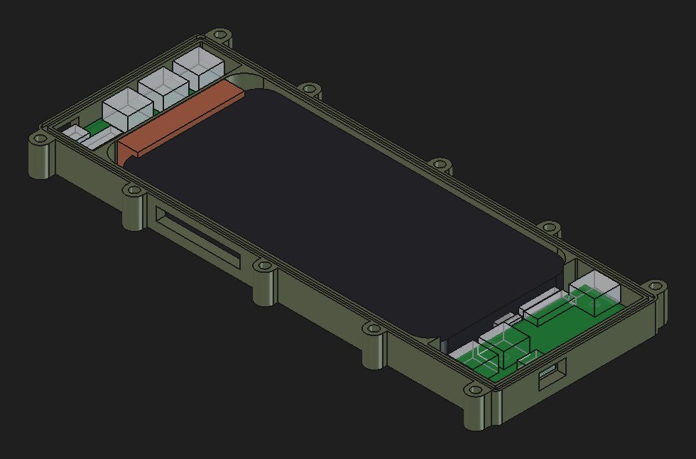
ATAK button case v4 with the lid off: the hub board and button board sit in the end wings around the phone, with the drop-in wedge at the phone's top end

Lid off: the hub board in one wing, the button board in the other, and the drop-in wedge holding the phone onto its USB-C plug.

Two custom boards

All of the electronics live on two boards I designed in KiCad. Both are finished, pass every design check, and are sitting in a folder ready to order from JLCPCB.

  • Hub board (right wing): the USB hub, the button controller, power for the phone, a data port out to the radio, and three buttons. It’s a 6-layer board only 0.8 mm thick. The USB-C plug that goes into the phone straddles the board edge with pins on both faces, and that one part only fits a 0.8 mm board.
  • Button board (left wing): three more buttons and the USB-C charge port. A 14-wire cable runs under the phone to tie the two together.
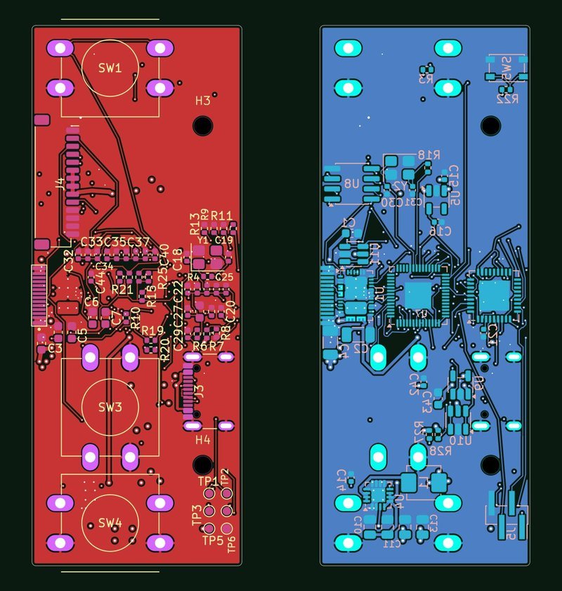
KiCad layout of the ATAK button case hub board, top and bottom, with three button switches, USB hub and controller chips

The hub board, top and bottom: a 6-layer, 0.8 mm board that plugs straight into the phone.

Where the print is

v3 got printed and strapped on. The overall shape and size sit well on the chest, so that stays. But the separate left-end piece felt fragile, and the slots for the phone’s own side buttons were a little off. So v4 changes how it goes together:

  • One-piece body with a screw-down front lid. Ten M3 cap screws into heat-set inserts, all outside the seal.
  • An o-ring cord seal around the lid joint. The ports and screen still need plugs and a film before I’d call it splash resistant.
  • A drop-in wedge that holds the phone onto its USB-C plug. The phone drops in, slides onto the plug, the wedge goes in behind it, and the lid goes on.
  • A bolt-on mount pod with the AMPS hole pattern, so the mount can be swapped.
  • The phone’s side-button slots moved to match the test print.

It grew a bit for all that: about 215 × 78 mm, roughly 30 mm thick with the pod. v4 is printing tonight on two printers at once, so I’ll have a usable one in hand either way.
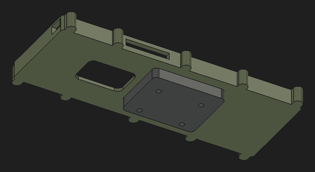
Back of the ATAK button case v4 showing the camera cutout and the bolt-on mount pod with AMPS hole pattern

Back side: a bolt-on pod with the AMPS hole pattern for the chest mount.

Coming up

  • How v4 prints and fits.
  • Ordering the boards, then the full build write-up with all the details.
  • Soft TPU button caps captured in the rigid print. That’s my own R&D project once the boards are in hand.
  • Mapping the buttons to ATAK functions.

This is a side build of the OpenMANET radio project. The latest radio work is in part 7: 5 GHz on the mesh.
Free STL: A Raspberry Pi 4 Test Stand for OpenMANET Nodes

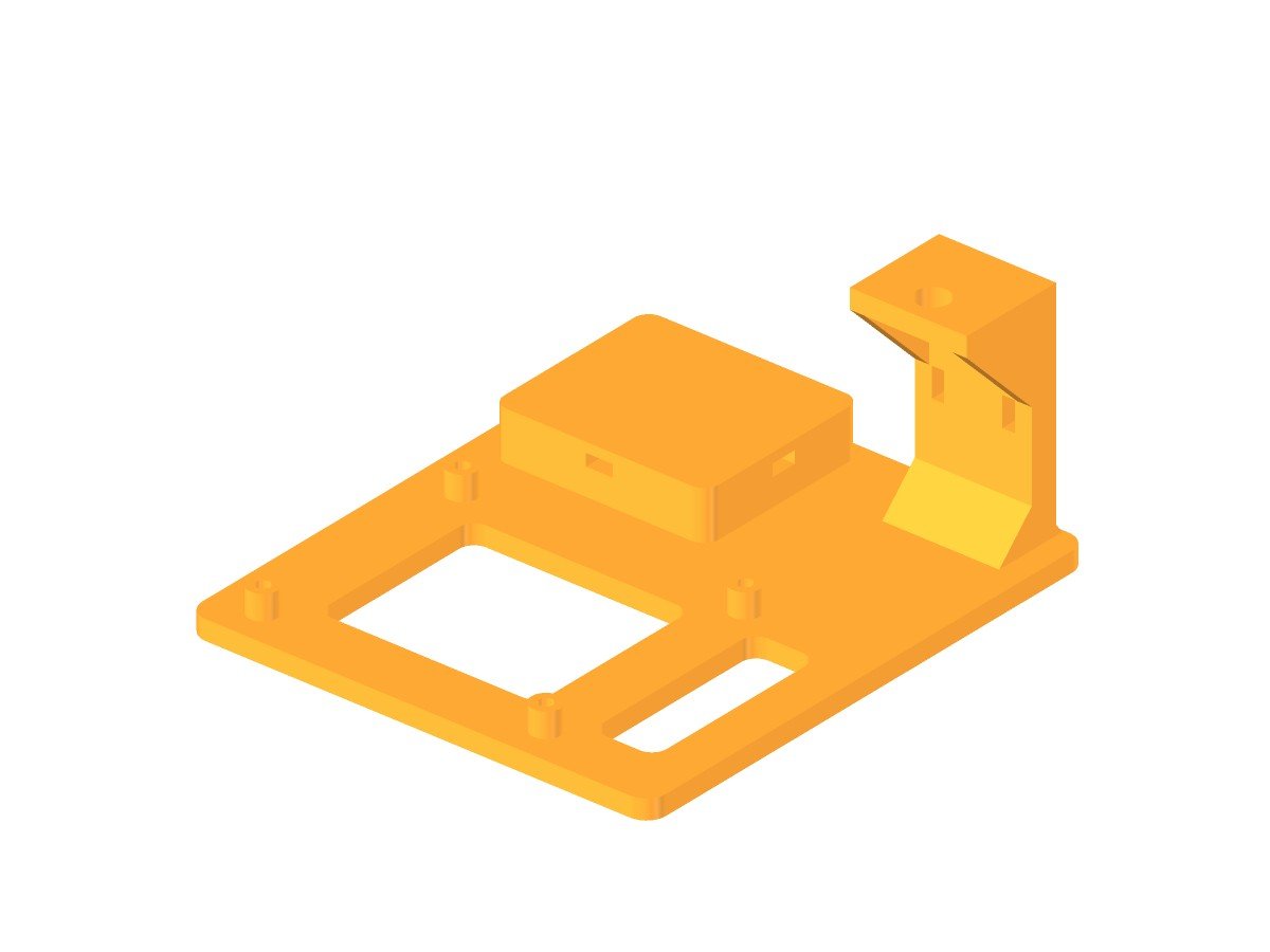
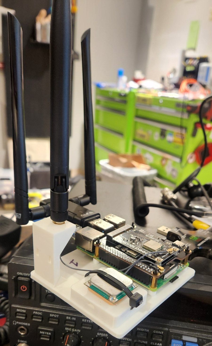
Two bench nodes with antennas flopping around on pigtails and a GPS puck sliding across the desk got old fast. So I made a quick Raspberry Pi 4 test stand to wrangle the mess until this stack moves into a real radio body. It printed once, fit the first time, and both nodes live on one now. Files are free at the bottom.

Printed white Raspberry Pi 4 test stand in use on the bench: Pi 4 with Seeed HaLow HAT, 915 MHz antenna upright on the tower, GPS module zip-tied to the pad, and an Alfa 5 GHz USB adapter plugged in

The real thing: node 1 on its stand, with the HaLow HAT, the 915 MHz antenna up on the tower, the GPS zip-tied down and the Alfa 5 GHz adapter plugged in.

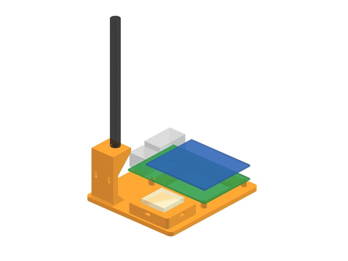
Raspberry Pi 4 test stand render with a see-through Pi 4, Seeed WM1302 HAT, GPS patch antenna and 915 MHz antenna in place

The stand with the node in place. The Pi, HAT, GPS patch and antenna are see-through reference parts.

What the Raspberry Pi 4 test stand holds

  • The Pi 4 and HAT on four 5 mm posts. All the Pi’s ports hang off the edges, so power, HDMI, USB, Ethernet and the SD card all stay reachable. Vent windows sit under the board.
  • The 915 MHz antenna, upright. A tower behind the stack has a shelf at 50 mm with a 6.6 mm hole. The SMA bulkhead goes up through it and the antenna screws on top, clear of the HAT.
  • The GPS antenna on a 44 × 38 mm pad with two crossed zip-tie tunnels just under the surface, so you can strap it either direction.
  • The u.FL pigtail ties off through two slots in the tower wall, so nothing pulls on the tiny connector.
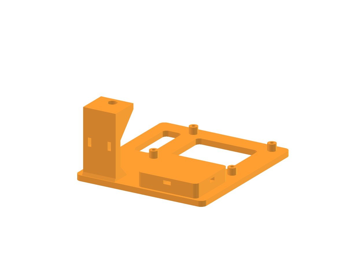
Raspberry Pi 4 test stand on its own: base plate with four standoff posts, vent windows, GPS pedestal and the antenna tower

The bare stand: four posts for the Pi, vent windows under the board, the GPS pad and the antenna tower.

Printing it

  • Prints flat on the bed, no supports. The shelf gussets are 45° and the shelf underside bridges about 18 mm.
  • About 57 cm³ of filament. Any material works; it’s a bench fixture.
  • Base is 95 × 108 × 4 mm. Print one per node.
Raspberry Pi 4 test stand antenna tower with the 6.6 mm SMA bulkhead hole in the shelf, pigtail zip-tie slots, and the GPS pad's zip-tie tunnel

Antenna tower: SMA bulkhead hole up top, zip-tie slots for the pigtail, and the GPS pad’s tie tunnel.

Hardware and assembly

  1. Swap the four short screws under the Pi for M2.5 × 12 mm screws. They go up through the recessed holes in the bottom of the stand, through the Pi, and thread into the HAT’s brass standoffs.
  2. Push the SMA bulkhead up through the shelf hole and put the nut on from above. Screw the antenna on.
  3. Zip-tie the u.FL pigtail through the tower slots.
  4. Set the GPS antenna on the pad and run a zip tie (up to about 4.8 mm wide) through either tunnel.
Underside of the Raspberry Pi 4 test stand showing the four recessed M2.5 screw holes and vent windows

Underside: recessed holes for the four M2.5 × 12 screws, plus the vent windows.

Fit notes

The 6.6 mm SMA hole (1/4-36 thread) was the one dimension I couldn’t confirm before printing. It fit my connectors on the first try, and so did the screw holes. If yours is tight or sloppy, the FreeCAD macro in the download has an SMA_D parameter at the top. Change it, run the macro, and it spits out a new STL.

Download the Raspberry Pi 4 test stand

The zip has the printable STL, the FreeCAD model (with the reference parts), the FreeCAD macro that rebuilds it from parameters, and a short README with these notes.

Download the test stand files (.zip, 121 KB)

It’s built around the Seeed WM1302 HAT and the stock OpenMANET phase 1 parts from part 3, but it’ll hold any Pi 4 with a HAT, an SMA antenna and a puck GPS.

—
TL;DR: A no-supports Raspberry Pi 4 test stand for OpenMANET bench nodes: Pi and HAT on posts, 915 MHz antenna upright on a tower, GPS zip-tied to a pad, pigtail tied off. Four M2.5 × 12 screws and a few zip ties. Free STL and FreeCAD files above.

The OpenMANET Handheld, Rendered: A CM4 Concept in FreeCAD

With two nodes meshing on the bench (part 4), I wanted to actually see the thing I keep describing. So I modeled the OpenMANET handheld in FreeCAD from every decision I’ve made so far and rendered it from all sides. This is a concept. The real dimensions get set by the CM4 carrier board, which doesn’t exist yet, so expect the body to change. But it’s a lot easier to argue with a picture than with a bullet list.

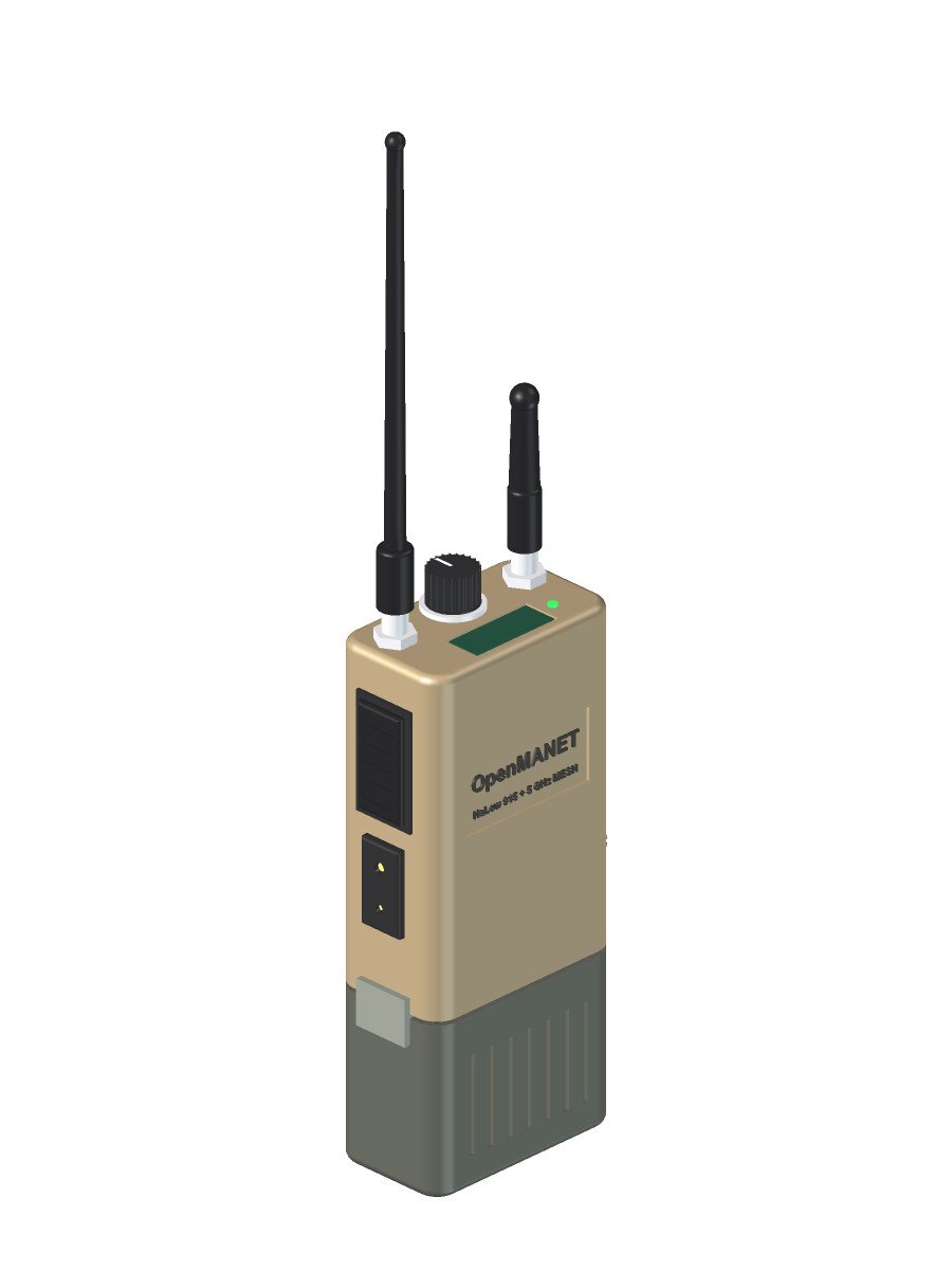
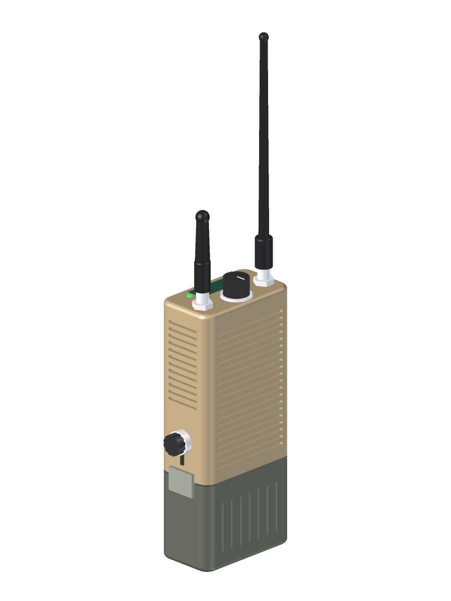
OpenMANET handheld concept render, three-quarter view: flat dark earth body with 915 MHz HaLow whip and 5 GHz stub antennas, channel knob, top status screen, side PTT and Kenwood 2-pin jack, battery pack below

Three-quarter view: PTT and Kenwood 2-pin jack on the left side, screen and channel knob up top.

The OpenMANET handheld envelope

The size target is Silvus SC4200EP territory: a body about 102 × 67 × 38 mm before connectors, with the battery hanging off the bottom. Yes, it’s tacticool. I’ve made my peace with that.

  • Printed shell, flat dark earth ASA. ASA because it handles sun and heat better than PLA or PETG.
  • The shell is the heatsink. Fins on the back and the right side, with a thermal pad from the CM4 to the inside wall. No fan.
  • Front face stays clean for a label and whatever ends up there once I hold it in my hand.
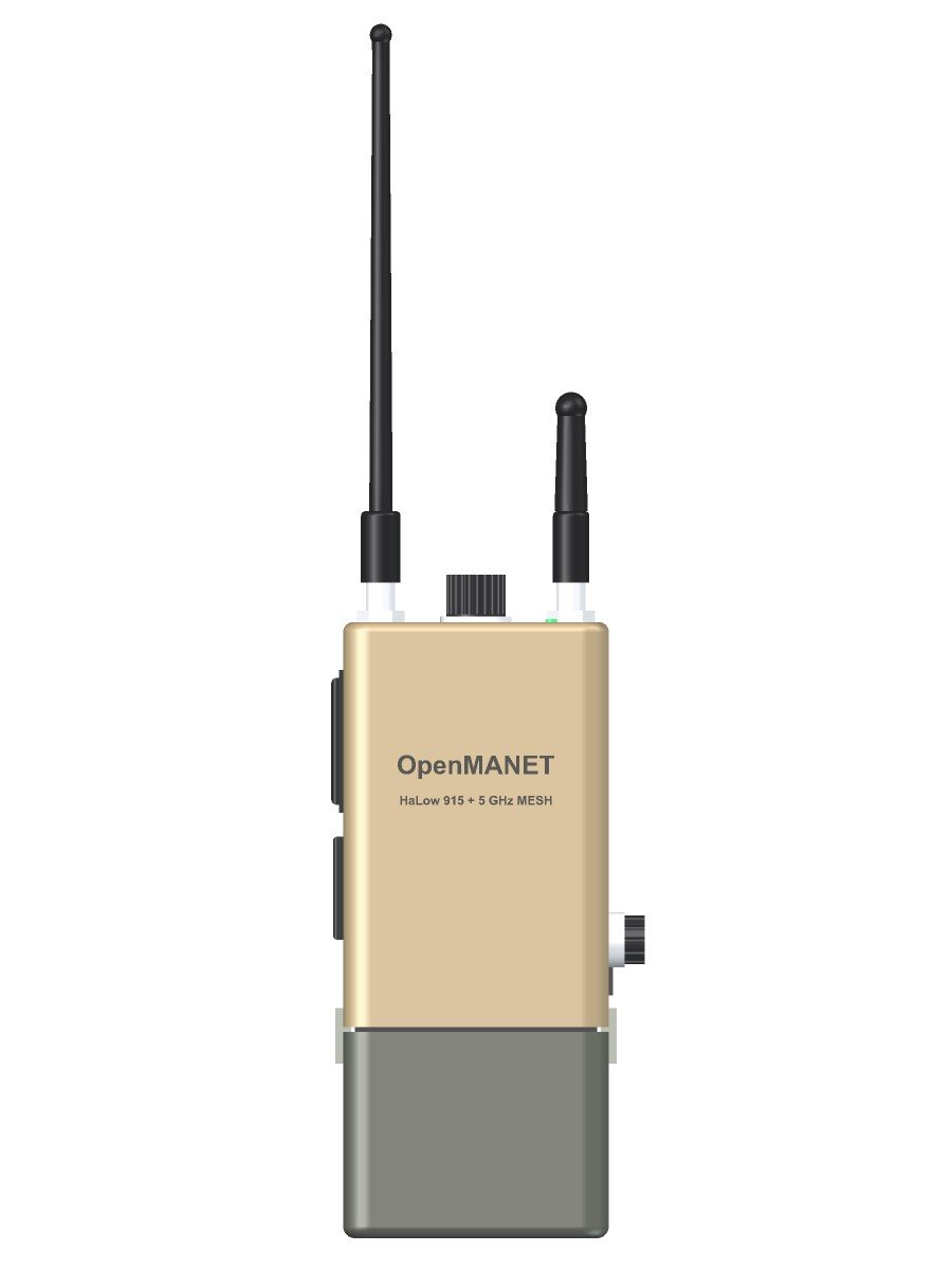
Front view render of the OpenMANET handheld concept showing the body, antenna layout, channel knob, data port and battery pack proportions

Straight-on front view. The body is about 102 × 67 × 38 mm, roughly SC4200EP-sized.

Top panel: two antennas, a knob and a screen

Everything you touch without looking lives on top.

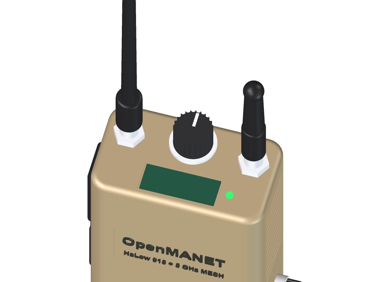
  • Two antenna ports. The tall whip is the 915 MHz HaLow mesh. The stubby one is the 5 GHz radio for the dual-band plan. Both are separate cards inside, not USB dongles.
  • A real channel knob. A detented rotary switch wired straight to GPIO picks the push-to-talk talk group. Click to channel 3, and you’re talking and listening on channel 3. No phone required.
  • A small status screen showing channel, mesh neighbors and signal. It has to be readable in direct sun, in the dark, and dim enough not to bloom under night vision. I haven’t picked the display that does all three yet.
  • A status LED for the at-a-glance “am I on the mesh” check.
Close-up render of the OpenMANET handheld top panel: HaLow and 5 GHz antenna connectors, knurled talk-group channel knob, status screen and status LED

Top panel: two antenna ports, the talk-group knob and a small status screen.

PTT side: push-to-talk and a Kenwood jack

In part 4 I ran push-to-talk from a phone browser. That’s great for testing, but a radio should work with the phone in your pocket.

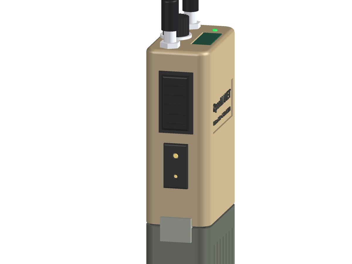
  • A big ribbed PTT bar on the left side where your thumb lands.
  • A Kenwood 2-pin accessory jack under it, so any standard speaker mic or earpiece plugs straight in. I rarely expect to use VOX.
  • Audio and PTT come from the OpenVLM design, the open-source CM108B USB audio board from the OpenMANET community. OpenMANET already auto-detects it, so hardware PTT works with stock software.
Side render of the OpenMANET handheld concept showing the ribbed push-to-talk button and Kenwood 2-pin accessory jack for a shoulder mic or earpiece

PTT side: a big ribbed push-to-talk bar over a Kenwood 2-pin jack for a speaker mic or earpiece.

Back and right side: fins and a data port

The back is all fins. The right side gets fins up high and a capped, sealed data port down low. That port is for the drone detection station: plug it in, and its bearings go out over the mesh as Cursor-on-Target to every ATAK screen.

Rear three-quarter render of the OpenMANET handheld concept showing heatsink fins on the back and right side and the capped data port for the drone DF station

Back side: fins on the back and right side, plus the capped data port for the drone DF station.

The swap-on battery

The whole point of putting the battery on the bottom is to swap it and keep going.

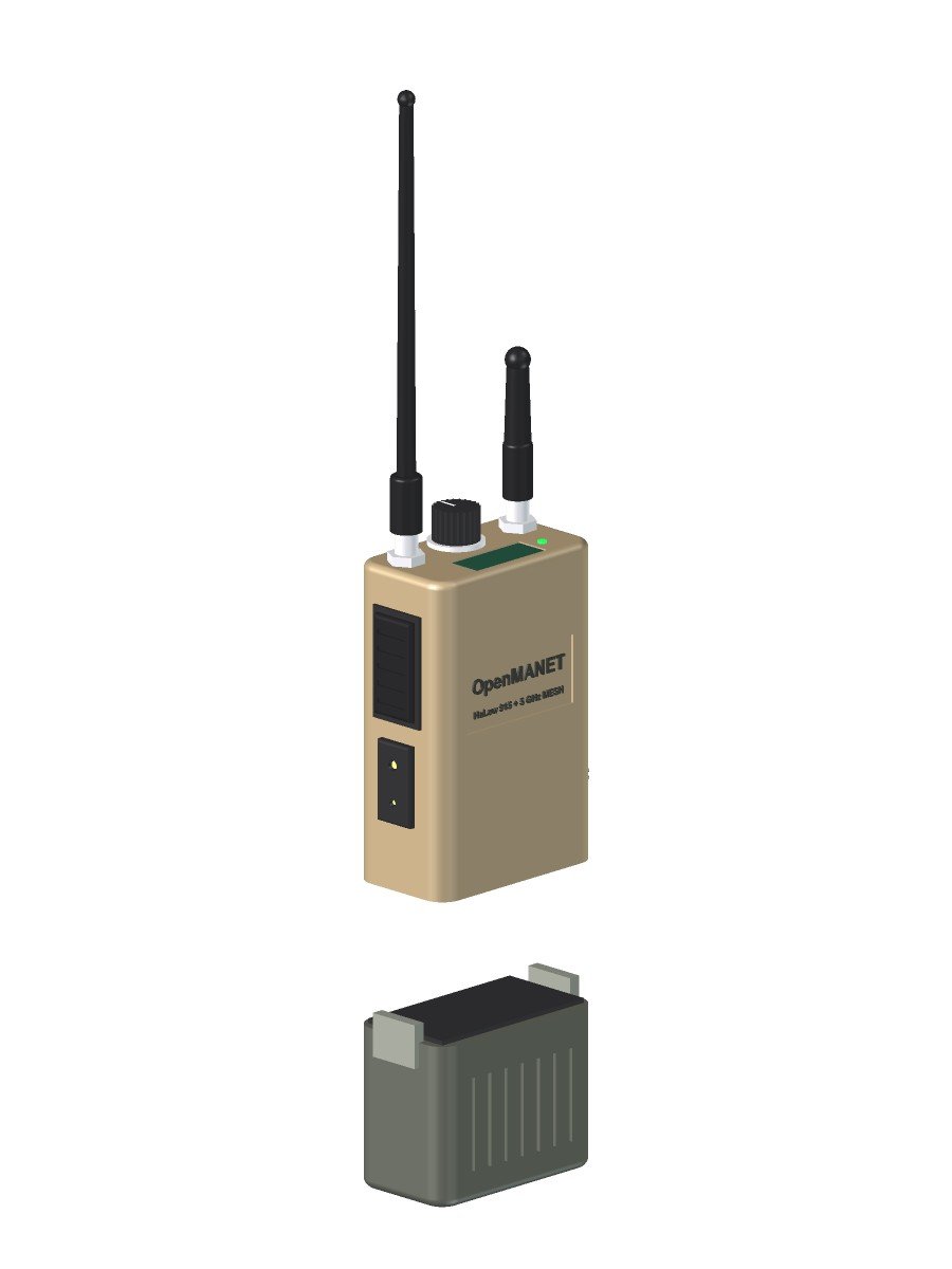
  • A PRC-148/152 (MBITR)-style interface. I’ll buy one adapter kit to learn the geometry, then 3D-print the mating faces on the radio and the pack and only buy the metal contacts from there.
  • Custom 3D-printed battery boxes, not off-the-shelf military batteries, with 21700 cells inside.
  • A small onboard backup cell keeps the radio alive for the few seconds the pack is off.
  • The pack design comes last. Its size and shape follow the body, so this block in the render is a placeholder for the volume.
Exploded render of the OpenMANET handheld concept with the swap-on battery pack pulled off the bottom, showing the MBITR-style mating face and side latches

Battery pack off: an MBITR-style interface on top of a custom 3D-printed pack, with side latches.

What’s inside (planned)

Block Plan
Computer Raspberry Pi CM4 with eMMC, on a custom KiCad carrier board
HaLow radio Gateworks GW16167 (Morse Micro MM8108) on an M.2 E-key slot
5 GHz radio PCIe M.2 card that supports 802.11s mesh (MT7916 family)
Audio / PTT OpenVLM CM108B design, out to the Kenwood 2-pin jack
Controls Rotary talk-group switch on GPIO, PTT, status screen, LED
Power Swap-on 21700 pack, small backup cell, power path on the carrier
Not included 5G modem. Too much heat, power and antenna for a handheld; that lives in the mesh gate or a future vehicle unit.

And a standing rule: encryption stays on. If I ever have to choose between more transmit power and keeping the mesh encrypted, encryption wins.

What these renders don’t settle

  • Real dimensions. The carrier board outline drives the body, so the board comes first.
  • Antenna spacing. Two radios a few centimeters apart on one lid need real isolation testing.
  • Heat. Whether a finned ASA shell can actually carry the CM4’s heat with two radios running is something to measure, not guess.
  • The screen and the exact connector part numbers.

The model is plain FreeCAD Part geometry, built so I can change the numbers and regenerate. These images come straight from FreeCAD’s viewer: no ray tracer, just honest-looking boxes. Next steps are the carrier board in KiCad and a range walk with the bench nodes.

—
TL;DR: I modeled the OpenMANET handheld concept in FreeCAD: SC4200EP-sized finned ASA body, HaLow whip plus 5 GHz stub, a GPIO talk-group knob, a sunlight- and NVG-friendly status screen, side PTT with a Kenwood 2-pin jack, a data port for the DF station, and an MBITR-style swap-on battery. Concept only; the carrier board sets the real size.