The OpenMANET Handheld, Rendered: A CM4 Concept in FreeCAD

With two nodes meshing on the bench (part 4), I wanted to actually see the thing I keep describing. So I modeled the OpenMANET handheld in FreeCAD from every decision I’ve made so far and rendered it from all sides. This is a concept. The real dimensions get set by the CM4 carrier board, which doesn’t exist yet, so expect the body to change. But it’s a lot easier to argue with a picture than with a bullet list.
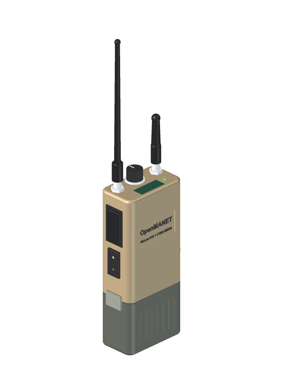
OpenMANET handheld concept render, three-quarter view: flat dark earth body with 915 MHz HaLow whip and 5 GHz stub antennas, channel knob, top status screen, side PTT and Kenwood 2-pin jack, battery pack below

Three-quarter view: PTT and Kenwood 2-pin jack on the left side, screen and channel knob up top.

The OpenMANET handheld envelope

The size target is Silvus SC4200EP territory: a body about 102 × 67 × 38 mm before connectors, with the battery hanging off the bottom. Yes, it’s tacticool. I’ve made my peace with that.

  • Printed shell, flat dark earth ASA. ASA because it handles sun and heat better than PLA or PETG.
  • The shell is the heatsink. Fins on the back and the right side, with a thermal pad from the CM4 to the inside wall. No fan.
  • Front face stays clean for a label and whatever ends up there once I hold it in my hand.
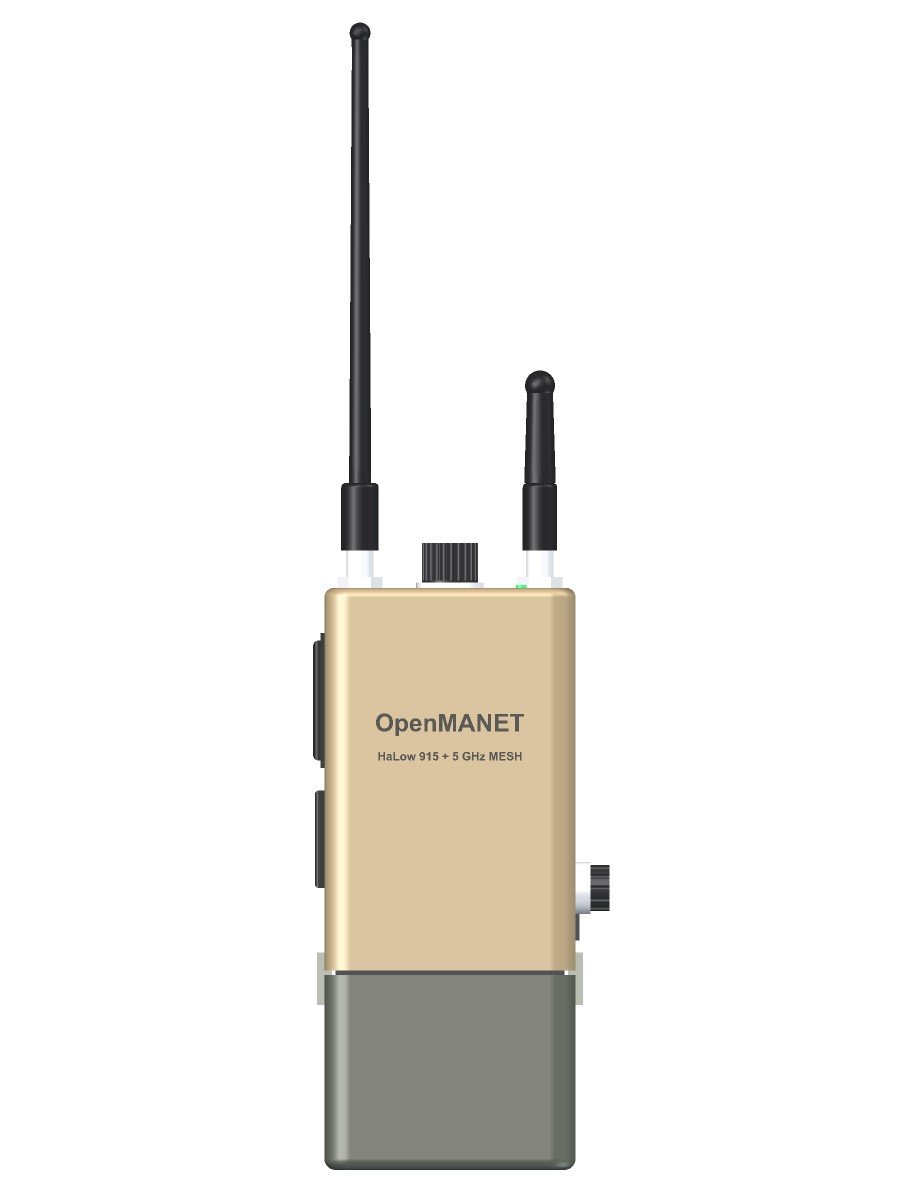
Front view render of the OpenMANET handheld concept showing the body, antenna layout, channel knob, data port and battery pack proportions

Straight-on front view. The body is about 102 × 67 × 38 mm, roughly SC4200EP-sized.

Top panel: two antennas, a knob and a screen

Everything you touch without looking lives on top.

  • Two antenna ports. The tall whip is the 915 MHz HaLow mesh. The stubby one is the 5 GHz radio for the dual-band plan. Both are separate cards inside, not USB dongles.
  • A real channel knob. A detented rotary switch wired straight to GPIO picks the push-to-talk talk group. Click to channel 3, and you’re talking and listening on channel 3. No phone required.
  • A small status screen showing channel, mesh neighbors and signal. It has to be readable in direct sun, in the dark, and dim enough not to bloom under night vision. I haven’t picked the display that does all three yet.
  • A status LED for the at-a-glance “am I on the mesh” check.
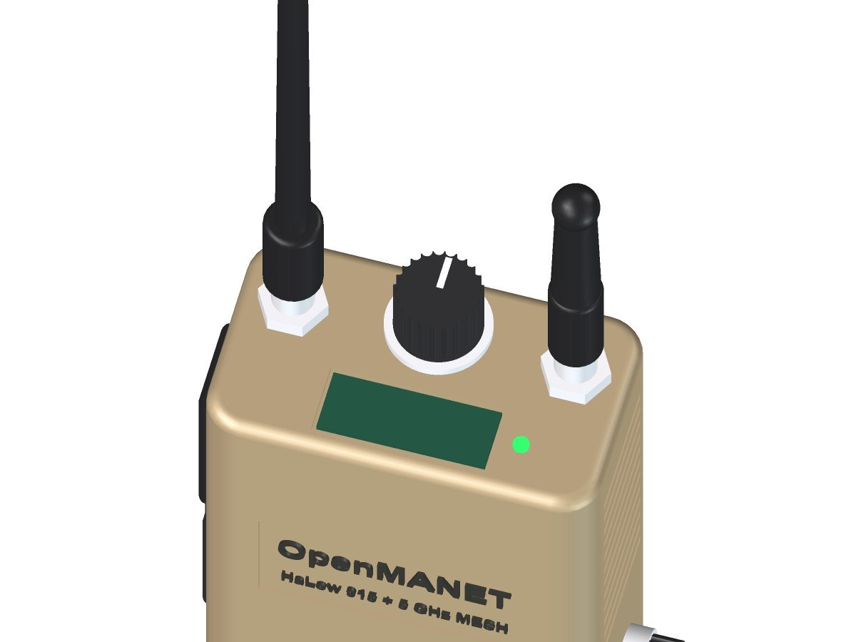
Close-up render of the OpenMANET handheld top panel: HaLow and 5 GHz antenna connectors, knurled talk-group channel knob, status screen and status LED

Top panel: two antenna ports, the talk-group knob and a small status screen.

PTT side: push-to-talk and a Kenwood jack

In part 4 I ran push-to-talk from a phone browser. That’s great for testing, but a radio should work with the phone in your pocket.

  • A big ribbed PTT bar on the left side where your thumb lands.
  • A Kenwood 2-pin accessory jack under it, so any standard speaker mic or earpiece plugs straight in. I rarely expect to use VOX.
  • Audio and PTT come from the OpenVLM design, the open-source CM108B USB audio board from the OpenMANET community. OpenMANET already auto-detects it, so hardware PTT works with stock software.
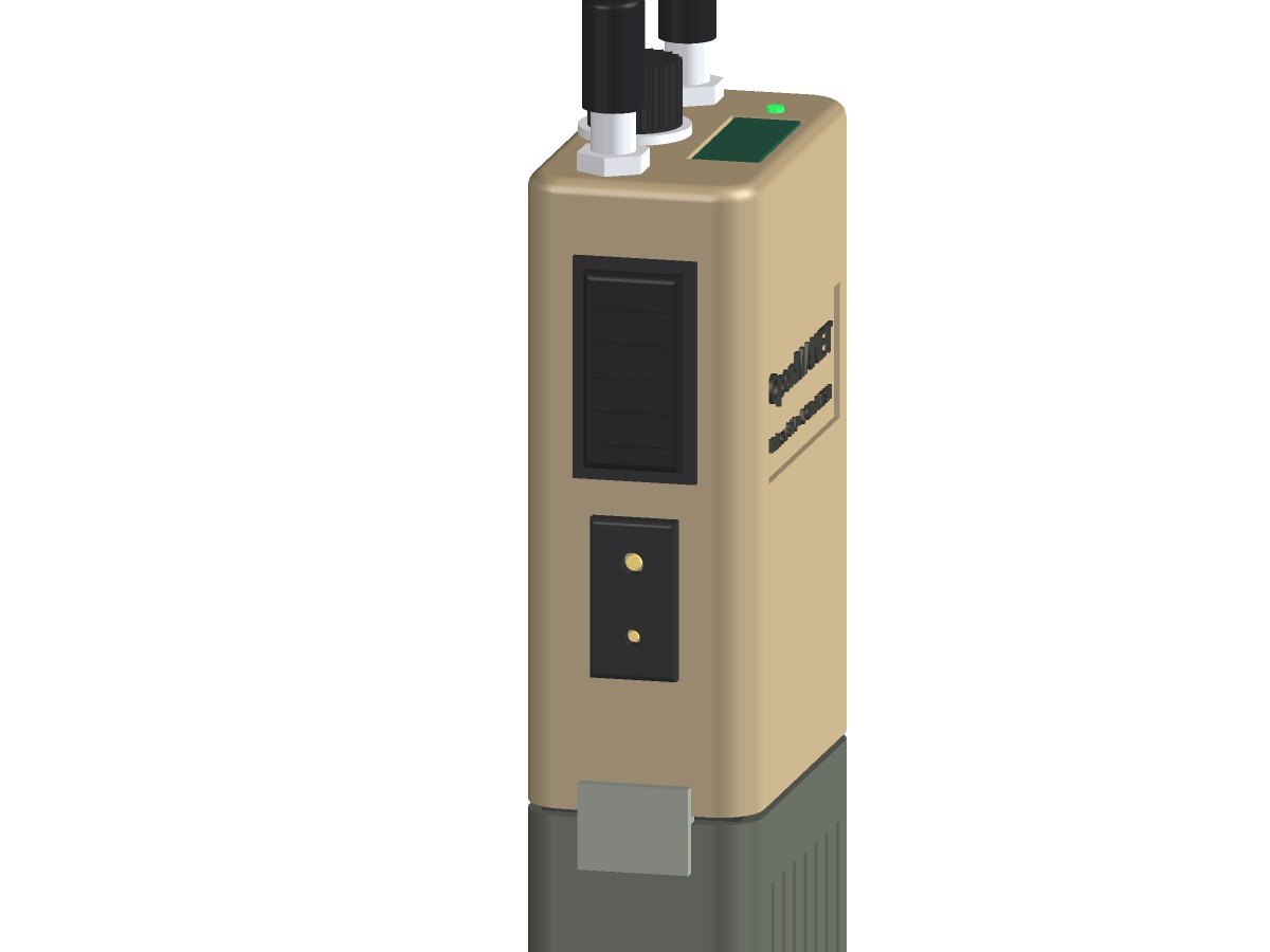
Side render of the OpenMANET handheld concept showing the ribbed push-to-talk button and Kenwood 2-pin accessory jack for a shoulder mic or earpiece

PTT side: a big ribbed push-to-talk bar over a Kenwood 2-pin jack for a speaker mic or earpiece.

Back and right side: fins and a data port

The back is all fins. The right side gets fins up high and a capped, sealed data port down low. That port is for the drone detection station: plug it in, and its bearings go out over the mesh as Cursor-on-Target to every ATAK screen.
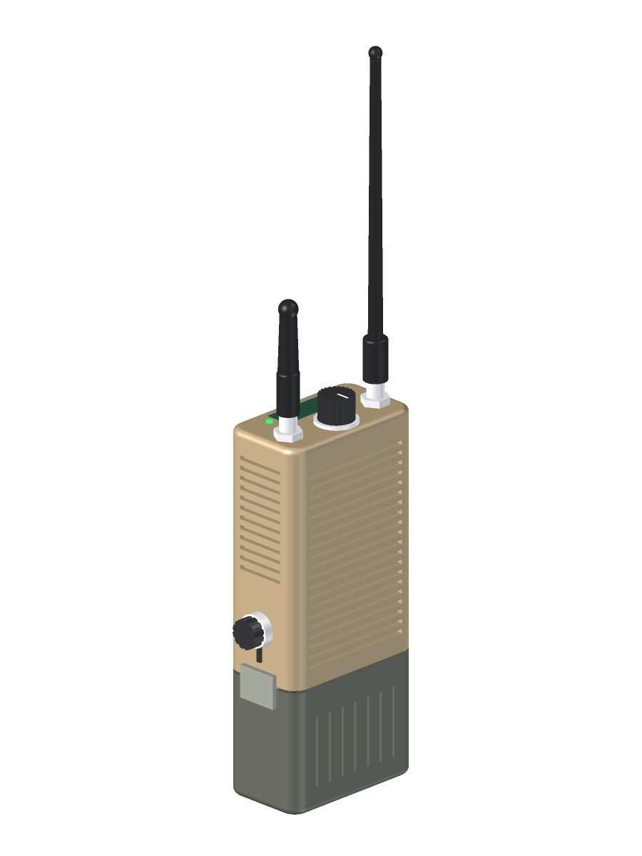
Rear three-quarter render of the OpenMANET handheld concept showing heatsink fins on the back and right side and the capped data port for the drone DF station

Back side: fins on the back and right side, plus the capped data port for the drone DF station.

The swap-on battery

The whole point of putting the battery on the bottom is to swap it and keep going.

  • A PRC-148/152 (MBITR)-style interface. I’ll buy one adapter kit to learn the geometry, then 3D-print the mating faces on the radio and the pack and only buy the metal contacts from there.
  • Custom 3D-printed battery boxes, not off-the-shelf military batteries, with 21700 cells inside.
  • A small onboard backup cell keeps the radio alive for the few seconds the pack is off.
  • The pack design comes last. Its size and shape follow the body, so this block in the render is a placeholder for the volume.
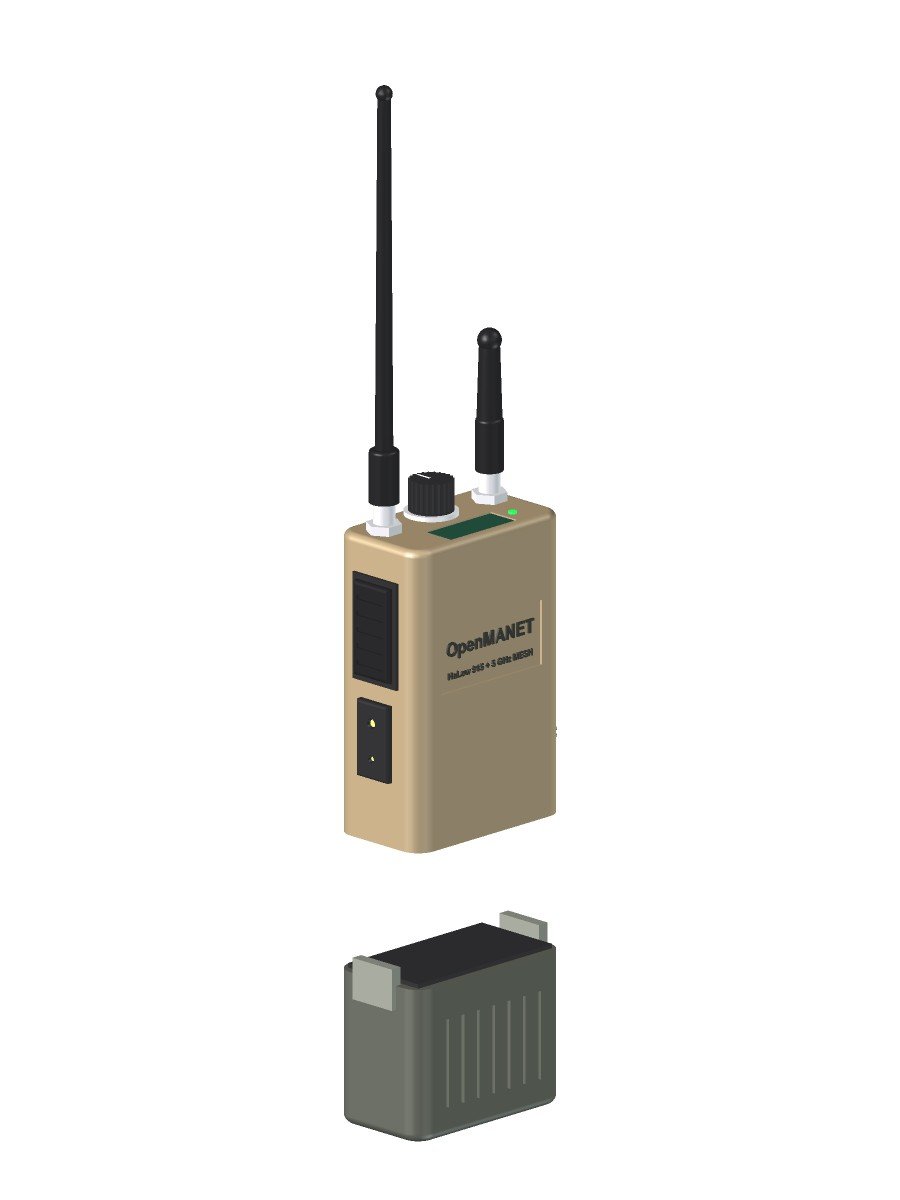
Exploded render of the OpenMANET handheld concept with the swap-on battery pack pulled off the bottom, showing the MBITR-style mating face and side latches

Battery pack off: an MBITR-style interface on top of a custom 3D-printed pack, with side latches.

What’s inside (planned)

Block Plan
Computer Raspberry Pi CM4 with eMMC, on a custom KiCad carrier board
HaLow radio Gateworks GW16167 (Morse Micro MM8108) on an M.2 E-key slot
5 GHz radio PCIe M.2 card that supports 802.11s mesh (MT7916 family)
Audio / PTT OpenVLM CM108B design, out to the Kenwood 2-pin jack
Controls Rotary talk-group switch on GPIO, PTT, status screen, LED
Power Swap-on 21700 pack, small backup cell, power path on the carrier
Not included 5G modem. Too much heat, power and antenna for a handheld; that lives in the mesh gate or a future vehicle unit.

And a standing rule: encryption stays on. If I ever have to choose between more transmit power and keeping the mesh encrypted, encryption wins.

What these renders don’t settle

  • Real dimensions. The carrier board outline drives the body, so the board comes first.
  • Antenna spacing. Two radios a few centimeters apart on one lid need real isolation testing.
  • Heat. Whether a finned ASA shell can actually carry the CM4’s heat with two radios running is something to measure, not guess.
  • The screen and the exact connector part numbers.

The model is plain FreeCAD Part geometry, built so I can change the numbers and regenerate. These images come straight from FreeCAD’s viewer: no ray tracer, just honest-looking boxes. Next steps are the carrier board in KiCad and a range walk with the bench nodes.

—
TL;DR: I modeled the OpenMANET handheld concept in FreeCAD: SC4200EP-sized finned ASA body, HaLow whip plus 5 GHz stub, a GPIO talk-group knob, a sunlight- and NVG-friendly status screen, side PTT with a Kenwood 2-pin jack, a data port for the DF station, and an MBITR-style swap-on battery. Concept only; the carrier board sets the real size.
My OpenMANET Dual-Band Plan: HaLow + 5 GHz, a CM4 Carrier and a Handheld

In part 1 I got the basics of OpenMANET straight. This one is the plan, and the headline is the OpenMANET dual-band idea: a mesh that runs fast 5 GHz links when nodes are close together and falls back to long-reach 915 MHz HaLow when they drift apart, without the network ever dropping. Plus a handful of other things I want bolted on. Writing it down now so I can see later how far off I was.

Ground rule: stay compatible with stock nodes

I want my radios to join anyone else’s OpenMANET mesh, and theirs to join mine. So everything custom is an add-on on top of the stock firmware, never a fork of the core. For a node to join a mesh, these have to match:

  1. HaLow mesh ID, encryption key, channel and channel width
  2. Country/regulatory settings (the radio’s BCF file), so channels and power line up
  3. A compatible batman-adv version
  4. The stock network model: 10.41.0.0/16, a DHCP scope per node, one mesh gate

Anything I add has to be invisible or harmless to a node that doesn’t know about it. Before I call any custom feature done, it gets tested against an untouched stock node.

How OpenMANET dual-band works: let batman-adv do it

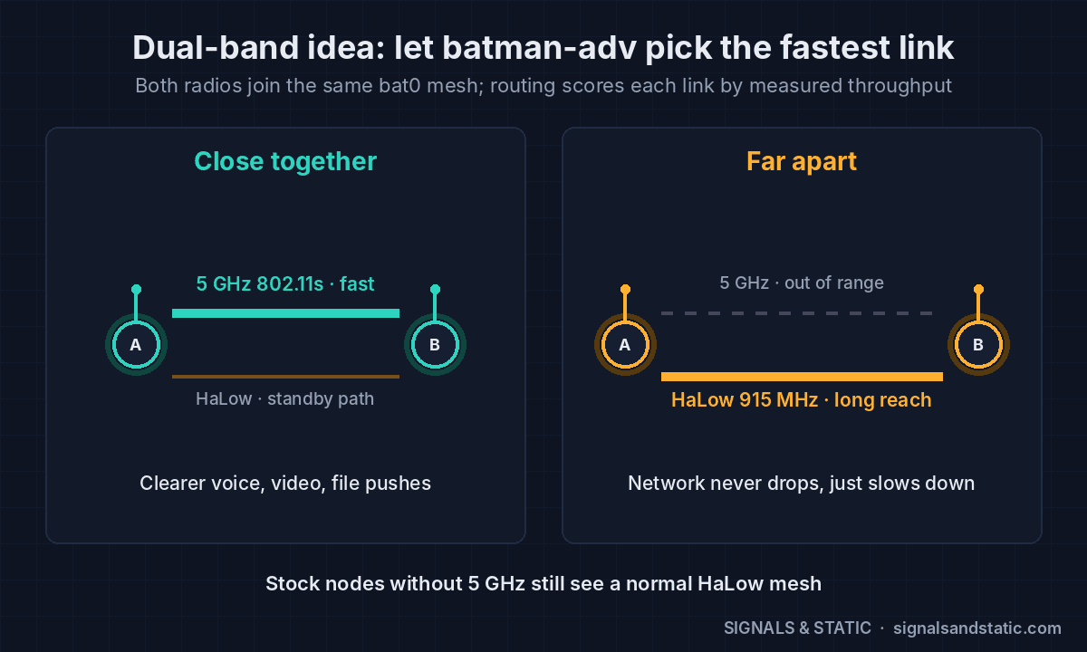
This turned out to be the easy part, because the mesh stack already supports it. batman-adv can bond several radio interfaces into one mesh. Add a 5 GHz 802.11s interface next to the HaLow one, attach both to the same bat0, and BATMAN_V picks routes by measured throughput.

  • Close together: the 5 GHz hop is way faster, so traffic moves onto it automatically. Clearer voice, video and file pushes.
  • Far apart: 5 GHz falls out of range and traffic falls back to HaLow. The network slows down; it doesn’t drop.
  • Stock nodes without a 5 GHz radio just see a normal HaLow mesh.

RTSP video, ATAK and file transfers get the benefit without knowing anything about it. They ride whichever link batman-adv picks.

OpenMANET dual-band diagram: close together, traffic rides a fast 5 GHz 802.11s link; far apart, batman-adv falls back to 915 MHz HaLow without dropping the mesh

Close in, batman-adv moves traffic onto 5 GHz. Far apart, it falls back to HaLow.

Not every 5 GHz radio can mesh

The radio has to support 802.11s mesh point mode, and a lot of popular cards don’t. Per the OpenMANET docs: the MT7916AED and MT7915DAN work (stability varies with kernel and driver), the QCA6174 works but only one network at a time, and the Intel AX200/AX210 and MT7921 are access-point only.

The Pi 4 only has USB for a second radio, so testing will use a MediaTek mt76-family USB adapter (MT7612U or MT7610U chips). Rule of thumb: shop by chip, not brand. Avoid MT7921-based Wi-Fi 6 sticks and Realtek RTL88xx adapters for mesh work. The final hardware gets a PCIe M.2 card (MT7916) on the CM4 board.

Voice that gets better when you’re close

Here’s the part I haven’t seen anyone else do. OpenMANET’s push-to-talk already uses Opus audio and adapts its error correction when packets drop. My add-on would go the other way: when every listener in a talk group is on a fast link, bump the Opus bitrate up for clearer audio, and drop back the moment anyone isn’t. Opus decoders follow bitrate changes on their own, so stock nodes still hear it fine.

Is anyone else doing this?

Multi-band mesh isn’t a new idea, to be fair:

  • OpenMANET upstream says work is underway to bond HaLow with 2.4 GHz using BATMAN_V. Same mechanism, different band, so I should talk to them before I start rather than duplicate their work.
  • Doodle Labs sells 900 MHz + 2.4 GHz Mesh Rider radios, but the whole mesh switches bands together to dodge interference. One band at a time, not a different band per link.
  • Silvus has a dual-band StreamCaster with a dual-frequency link feature. Proprietary, and military money.

What’s less common in mine is HaLow plus 5 GHz picked per link, voice that improves when nodes are close, and staying fully open and compatible with stock nodes. The adaptive voice piece is a good candidate to contribute back.

The other add-ons

  • 5G mesh gate. One node NATs the whole mesh onto the internet through the Quectel RM520N-GL 5G modem I pulled out of a swap-meet box. Its GNSS can supply that node’s position. On a Pi 4 it needs a USB 3 sled, since the PCIe HAT I was eyeing is Pi 5-only and OpenMANET targets the Pi 4 and CM4.
  • Drone DF link. My drone detection stations would plug into a node’s Ethernet port and publish bearings as Cursor-on-Target, so they show up on every ATAK screen on the mesh. Two stations could share bearings for triangulation over the same mesh. It’s all just IP, so the radio core doesn’t change.

The hardware end state: a CM4 handheld

I’ll admit it: I want it to look like a real tactical radio. The inspiration is something like the Silvus SC4200EP handheld, with a vehicle unit later once the hardware and software settle. I know it’s tacticool. I think they look cool. Moving on.

The CM4 is the same silicon as the Pi 4, so OpenMANET support and power draw carry over, but it exposes a PCIe lane the Pi 4 board doesn’t. A custom carrier board in KiCad could put all of this on one board:

  • CM4 with onboard eMMC (no SD card to shake loose in the field)
  • The HaLow card and a PCIe 5 GHz card on M.2 slots
  • GPS, power management and SMA connectors laid out the way I want
  • A removable battery pack that clips onto the bottom, so I can swap and keep going, plus a small onboard backup cell to stay alive during the swap
  • A PRC-148/152-style battery interface. Plan is to buy one adapter kit to learn the geometry, then 3D-print the radio and battery sides and only buy the metal contacts after that.

No 5G modem in the handheld. Too many antennas, too much heat and power for something you carry. That lives in the mesh gate and maybe the vehicle unit.

The roadmap

  1. Two stock Pi 4 nodes. Learn the system, bench test, range test.
  2. Add 5 GHz. Prove dual-band switching on USB adapters.
  3. 5G mesh gate with the RM520N-GL.
  4. CM4 carrier board in KiCad.
  5. Handheld enclosure in FreeCAD, then the battery packs.
  6. Drone DF link once that project is far enough along.
OpenMANET build roadmap in six steps: stock Pi 4 nodes, 5 GHz, 5G mesh gate, CM4 carrier board, handheld enclosure and drone DF link, with the stay-compatible ground rule

Six phases, one rule: every node has to join anyone’s stock OpenMANET mesh.

Everything in this stack is unlicensed: HaLow and 5 GHz Wi-Fi are Part 15, and the 5G modem rides a carrier’s license. Next up: the phase 1 parts list.

References

—
TL;DR: Bond a 5 GHz radio and the HaLow radio into one batman-adv mesh and routing picks the fast link automatically. Add adaptive voice, a 5G gate and a DF port, then shrink it all onto a CM4 board in a handheld, while staying compatible with stock OpenMANET.