OpenMANET 5 GHz: Bonding a Second Band Into the Mesh (Results, Breakage and What’s Left)

The two Alfa adapters showed up today, so the dual-band plan stopped being a plan. I spent the day adding OpenMANET 5 GHz links to both bench nodes, changing the routing stack to suit, and running every speed, failover and power test I could think of. Some of it worked better than I hoped. One part locked a node up hard. Here’s all of it, plus what’s still left to test.
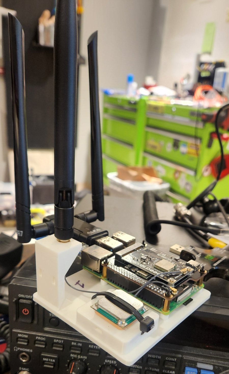
Raspberry Pi 4 OpenMANET node on its printed test stand with the HaLow HAT, 915 MHz antenna, GPS and the Alfa 5 GHz USB adapter plugged into a blue USB 3 port

Node 1 on its test stand, with the Alfa 5 GHz adapter riding in a blue USB 3 port.

The hardware: a stand-in 5 GHz radio

The handheld will use an MT7916 card on PCIe. The Pi 4 only has USB, so for bench testing I’m using an Alfa AWUS036ACM (MediaTek MT7612U) on each node. That chip uses the mainline mt76 driver and supports 802.11s mesh point mode, which is the whole point. The Pi’s onboard Wi-Fi stays as the client access point on channel 36.

What I changed in the OpenMANET routing stack

Everything sits on top of stock OpenMANET 1.8.0. Nothing in the core is forked, so a stock node still joins the HaLow mesh like normal.
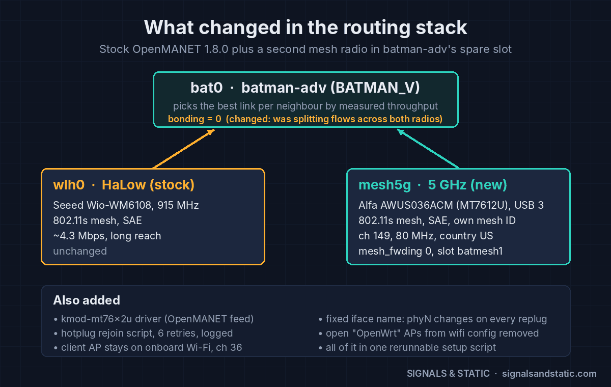
OpenMANET 5 GHz routing stack diagram: batman-adv bat0 with bonding off, the stock HaLow wlh0 interface and the new mesh5g 5 GHz interface on channel 149

One batman-adv mesh, two radios: stock HaLow plus the new mesh5g interface.

Change Why
Installed kmod-mt76x2u from OpenMANET’s package feed The Alfa’s driver isn’t in the 1.8.0 image.
Radio set to country US, channel 149, 80 MHz Without a country code, every 5 GHz channel is listen-only. Channel 149 (UNII-3, no DFS) stays well clear of the client AP on 36.
New 802.11s interface, mesh5g: SAE-encrypted, its own mesh ID, mesh_fwding 0 batman-adv does the multi-hop forwarding, so the Wi-Fi layer shouldn’t.
Attached to batmesh1, OpenMANET’s spare bat0 slot Both radios become interfaces of the same mesh. BATMAN_V scores each link by measured throughput and picks per neighbor.
Fixed interface name The phy number changes every time a USB radio is replugged, which broke everything keyed to it.
bonding = 0 on bat0 With bonding on, batman split transfers across both radios and lost about 35% of the speed (see below).
Removed the open “OpenWrt” access points that wifi config creates They’d broadcast an unsecured network.
Hotplug rejoin script, kept across firmware upgrades The Alfa doesn’t rejoin the encrypted mesh on its own after a replug. The script retries up to six times and logs each attempt.

All of that now lives in one setup script that’s safe to rerun (it has to be after a firmware upgrade, which drops the driver package) and a matching removal script that puts a node back to HaLow only.

Speed: OpenMANET 5 GHz vs HaLow

Nodes about a room apart, 5 GHz signal around −49 to −51 dBm, PHY rates 526–702 Mbps:
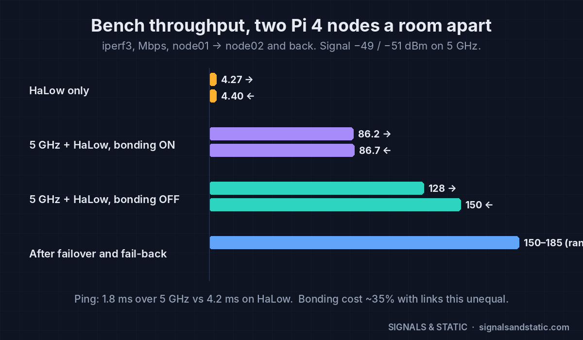
OpenMANET 5 GHz throughput chart: HaLow alone about 4.3 Mbps, 5 GHz with bonding on about 86 Mbps, bonding off 128 to 150 Mbps, after fail-back 150 to 185 Mbps

Bench throughput between the two nodes. Turning bonding off was worth about 35%.

Setup node01 → node02 node02 → node01
HaLow only 4.27 Mbps 4.40 Mbps
5 GHz + HaLow, bonding on 86.2 Mbps 86.7 Mbps
5 GHz + HaLow, bonding off 128 Mbps 150 Mbps
Ping 1.8 ms over 5 GHz vs 4.2 ms on HaLow

Roughly 30–35 times faster up close, which is exactly the “fast when close, long when far” idea. Radio retries were about 3%.

Why bonding hurt: bonding round-robins packets across every link to a neighbor. When one link is 30× slower than the other, the slow one drags the whole transfer down. With bonding off, batman just uses the best link, and the HaLow link sits there as the fallback.

Failover and fail-back

With a ping running once a second, I killed the 5 GHz radio and watched what batman did.
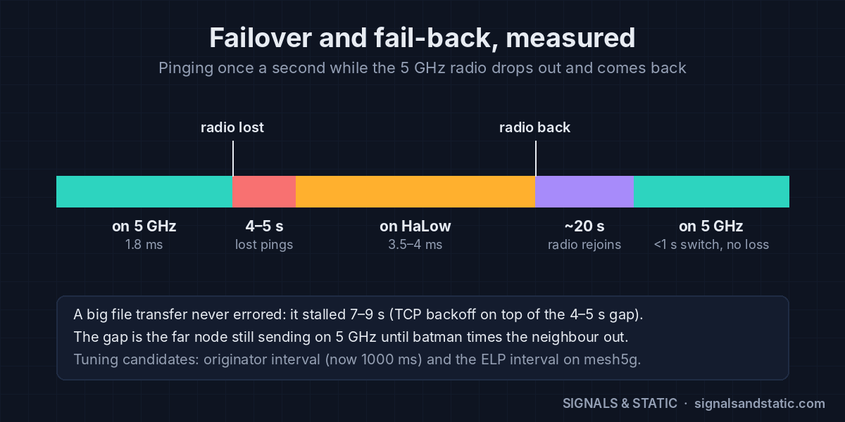
OpenMANET 5 GHz failover timeline: 4 to 5 seconds of lost pings when the 5 GHz radio drops, running on HaLow, about 20 seconds to rejoin, then back on 5 GHz in under a second with no loss

Failover to HaLow costs 4–5 s; failing back costs nothing once the radio has rejoined.

  • Failover to HaLow: 4–5 seconds of lost pings, then steady on HaLow at 3.5–4 ms. The gap is the far node still sending over 5 GHz until batman times out that neighbor.
  • Transfers survive: a running iperf transfer never errored. It stalled 7–9 seconds (TCP backing off on top of the routing gap) and then kept going on HaLow.
  • Fail-back: once the 5 GHz neighbor reappears, batman moves the live transfer back within a second, with no loss. The slow part is the radio rejoining the encrypted mesh, about 20–23 seconds after it comes back.

The hardships

1. Too close is too loud

With the two Alfas side by side, the signal was −23 dBm and the receivers overloaded. One direction collapsed to 12.7 Mbps with heavy retransmits. Moving the nodes a room apart fixed it. The sweet spot on the bench is −40 to −60 dBm.

2. ip link down/up doesn’t rejoin the mesh

Bouncing the mesh interface the Linux way leaves it down as far as the encrypted mesh is concerned. Use wifi, or batctl if del/add to pull it out of batman instead.

3. The adapter wouldn’t rejoin after a replug

The first hotplug script brought the Alfa back two times out of three. The second version retries up to six times, checks that the interface is really up before it quits, and logs every attempt.

4. A kernel lockup from pulling the USB radio

This was the big one. On roughly the fourth hot-unplug, node 1 locked up. The Alfa’s driver timed out with traffic still queued, then the node’s attempt to remove mesh5g from bat0 hung inside the kernel and couldn’t be killed. Every batman query after that piled up behind it: load average hit 2,188, the web UI sat on “Loading…”, and the rejoin script never got to run. SSH still worked, which is how I caught the evidence before a forced reboot.

It looks like a race between a USB radio vanishing and batman removing it (batman-adv 2025.4, mt76x2u, OpenMANET 1.8.0). It happened about one unplug in four.

Does it matter? Not for the handheld: the MT7916 is a PCIe card, and you can’t yank it out of a running radio. In the field, links fail by going out of range, and batman handles that cleanly. But for the Pi-based base and vehicle units that will keep using USB adapters, the rules are now: power off before unplugging, and strain-relieve the cable so a bump can’t pull it.

5. Smaller gotchas

  • Saving the Wireless page in the OpenMANET web UI can rewrite the wireless config and drop mesh5g. Don’t.
  • Any wifi command drops the web terminal session. Refresh and log back in.

Coexistence and real-world traffic

I ran a phone speed test to the internet through the mesh (node 1 is the gate on my home connection):

Phone connected to Down Up Ping
Node 1’s AP (direct to the gate) 81.6 Mbps 37.5 Mbps 15 ms
Node 2’s AP (AP ch 36 → 5 GHz mesh ch 149 → gate) 68.8 Mbps 13.2 Mbps 16 ms
Node 2’s AP, with a bulk transfer running 4.8 Mbps 2.9 Mbps –

The client AP on channel 36 and the mesh on channel 149 coexist fine on one node. Two things don’t add up yet:

  • Upload through node 2 is low (13.2 Mbps) even though the phone’s own link was 390 Mbps. My first suspect is fragmentation or MTU on the 5 GHz mesh interface.
  • One bulk flow starves everything else. With a 157 Mbps transfer running, the phone dropped to under 5 Mbps. My best guess: batman wraps all traffic to a neighbor in one outer header, so the Wi-Fi driver’s per-flow fair queuing sees a single giant flow.

Push-to-talk under load: clean

The good news: browser PTT between the nodes stayed clear both ways during a 90-second transfer, and the transfer still ran at 133 Mbps. PTT is multicast, and batman floods multicast out of both radios, so a copy of every voice packet rides the idle HaLow link and the far node plays whichever arrives first. Voice is protected today. Unicast traffic like ATAK, video and phone internet is not. And flooding every voice packet on both bands won’t scale forever, so that gets revisited with more nodes.

Power
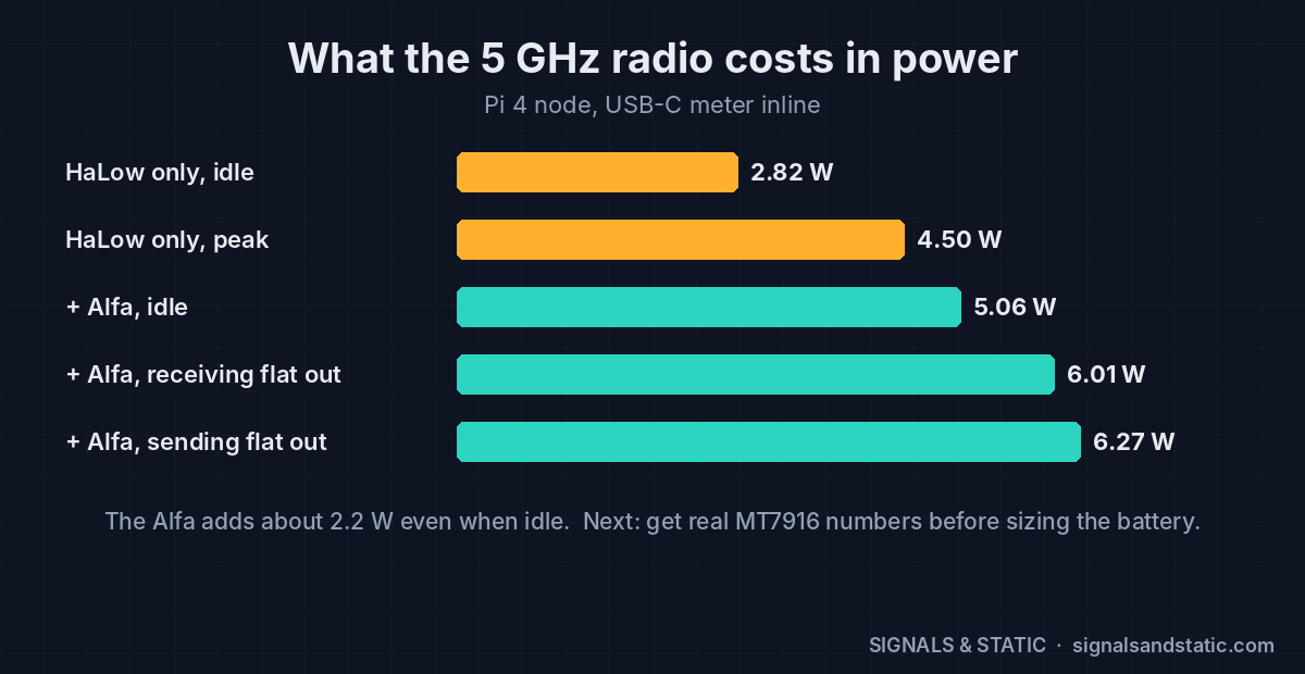
Power draw chart for an OpenMANET Pi 4 node: 2.82 W idle on HaLow only, 5.06 W idle with the Alfa 5 GHz adapter, up to 6.27 W sending at full speed

The 5 GHz adapter adds about 2.2 W even sitting idle.

With a USB-C meter inline on node 1: 5.06 W idle with both meshes up, 6.01 W receiving flat out, and 6.27 W sending flat out. Without the Alfa it was 2.82 W idle. That ~2.2 W idle cost matters for the handheld: on the battery I’ve been sketching, it could cut idle runtime from roughly 9 hours to 5 if the MT7916 draws like the Alfa. So I need real MT7916 numbers before the pack size is final. Shutting the 5 GHz radio down when no 5 GHz neighbors are around is on the idea list.

Remaining tests

  1. Prove the scripts: remove 5 GHz from node 2 with the removal script, then add it back from the gate with one command.
  2. Boot without the 5 GHz radio and mix with a stock node: the node with its radio removed acts as stock OpenMANET. The mesh and PTT need to keep working with no route flapping. The script test above covers this too.
  3. Upload and MTU check: track down the low upload through node 2.
  4. Voice bitrate: run PTT at higher Opus bitrates over 5 GHz vs HaLow. This is groundwork for the adaptive-voice idea.
  5. Outdoor walk test with GPS logging: carry node 2 away from the house while talking. It shows where 5 GHz hands off to HaLow and back, whether the audio hiccups during a soft failover, and finally gives me a HaLow range baseline.
  6. Save everything and reset: configs and logs off both nodes, nodes back to a known state.

Open issues to chase after that: the bulk-flow starvation (check whether voice packets carry DSCP EF so the Wi-Fi voice queue can help), tuning the 4–5 second failover gap (the originator interval is 1000 ms, and the ELP interval on mesh5g is a candidate), and MT7916 power figures.

Dropped: the USB 2 vs USB 3 comparison. Every future Pi unit will run its Alfa from a blue USB 3 port anyway, and moving the adapter means redoing the radio config for the new port.

—
TL;DR: A 5 GHz mesh link bonded into batman-adv next to HaLow (bonding off) took the bench nodes from 4.3 Mbps to 128–185 Mbps. Failover to HaLow costs 4–5 seconds, and transfers survive it. Pulling the USB radio from a running node can lock up the kernel, which the PCIe handheld won’t care about. Bulk traffic starves other users, but PTT stays clean because it rides both bands. Next up: script tests, stock interop, MTU, voice bitrate and an outdoor walk test.
Free STL: A Raspberry Pi 4 Test Stand for OpenMANET Nodes

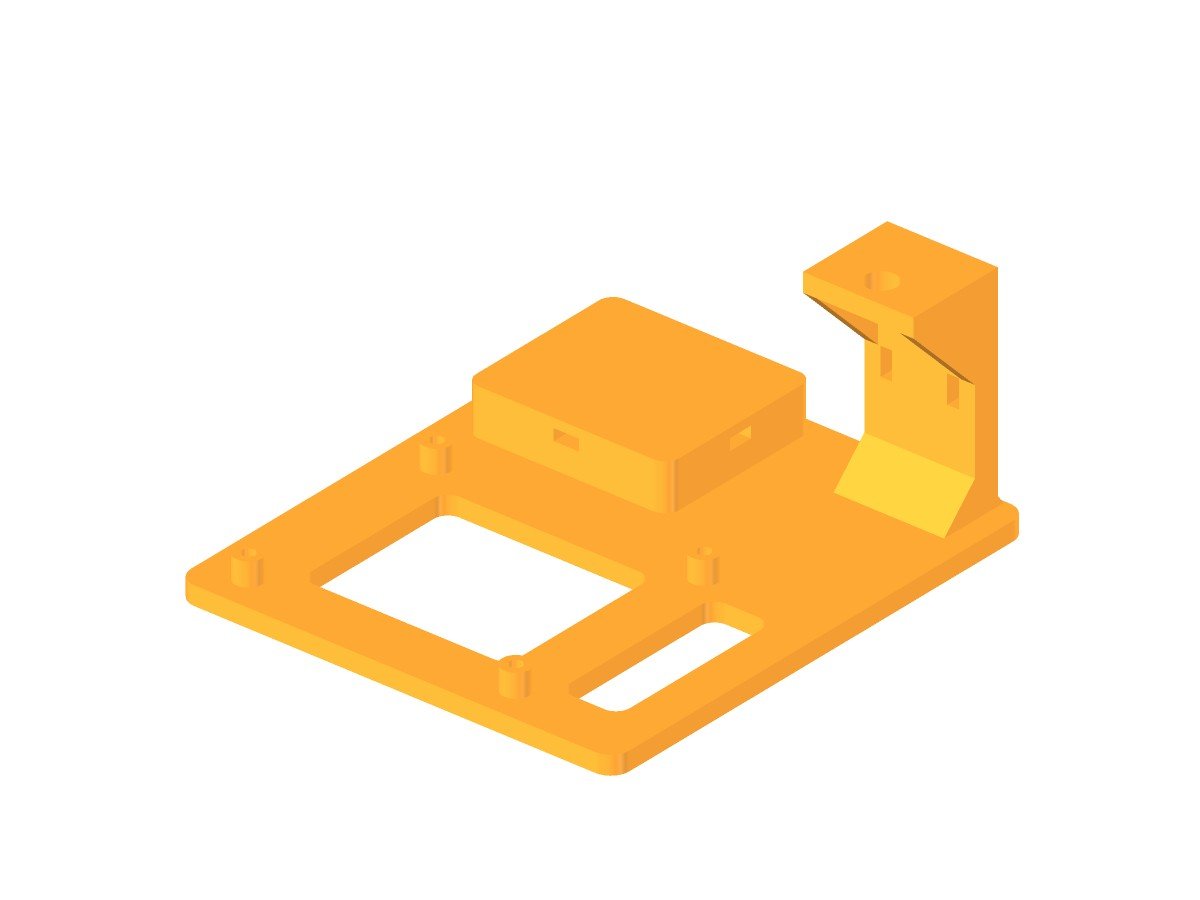
Two bench nodes with antennas flopping around on pigtails and a GPS puck sliding across the desk got old fast. So I made a quick Raspberry Pi 4 test stand to wrangle the mess until this stack moves into a real radio body. It printed once, fit the first time, and both nodes live on one now. Files are free at the bottom.

Printed white Raspberry Pi 4 test stand in use on the bench: Pi 4 with Seeed HaLow HAT, 915 MHz antenna upright on the tower, GPS module zip-tied to the pad, and an Alfa 5 GHz USB adapter plugged in

The real thing: node 1 on its stand, with the HaLow HAT, the 915 MHz antenna up on the tower, the GPS zip-tied down and the Alfa 5 GHz adapter plugged in.

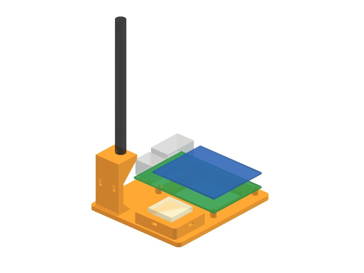
Raspberry Pi 4 test stand render with a see-through Pi 4, Seeed WM1302 HAT, GPS patch antenna and 915 MHz antenna in place

The stand with the node in place. The Pi, HAT, GPS patch and antenna are see-through reference parts.

What the Raspberry Pi 4 test stand holds

  • The Pi 4 and HAT on four 5 mm posts. All the Pi’s ports hang off the edges, so power, HDMI, USB, Ethernet and the SD card all stay reachable. Vent windows sit under the board.
  • The 915 MHz antenna, upright. A tower behind the stack has a shelf at 50 mm with a 6.6 mm hole. The SMA bulkhead goes up through it and the antenna screws on top, clear of the HAT.
  • The GPS antenna on a 44 × 38 mm pad with two crossed zip-tie tunnels just under the surface, so you can strap it either direction.
  • The u.FL pigtail ties off through two slots in the tower wall, so nothing pulls on the tiny connector.
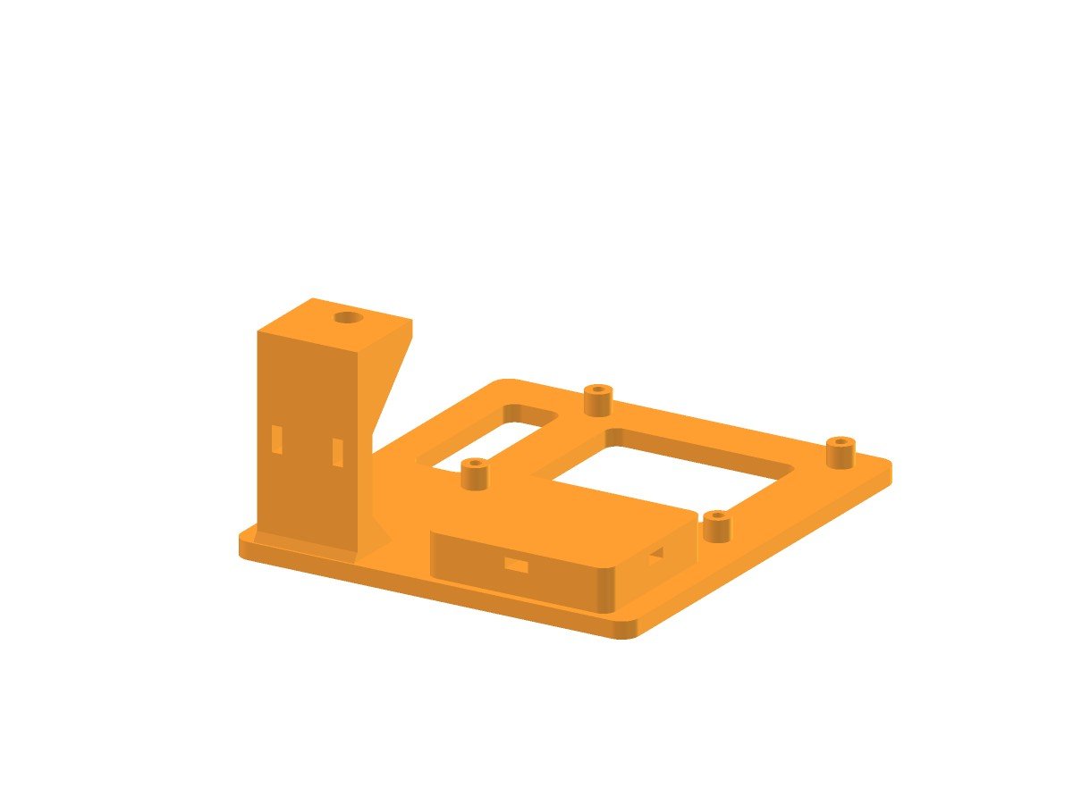
Raspberry Pi 4 test stand on its own: base plate with four standoff posts, vent windows, GPS pedestal and the antenna tower

The bare stand: four posts for the Pi, vent windows under the board, the GPS pad and the antenna tower.

Printing it

  • Prints flat on the bed, no supports. The shelf gussets are 45° and the shelf underside bridges about 18 mm.
  • About 57 cm³ of filament. Any material works; it’s a bench fixture.
  • Base is 95 × 108 × 4 mm. Print one per node.
Raspberry Pi 4 test stand antenna tower with the 6.6 mm SMA bulkhead hole in the shelf, pigtail zip-tie slots, and the GPS pad's zip-tie tunnel

Antenna tower: SMA bulkhead hole up top, zip-tie slots for the pigtail, and the GPS pad’s tie tunnel.

Hardware and assembly

  1. Swap the four short screws under the Pi for M2.5 × 12 mm screws. They go up through the recessed holes in the bottom of the stand, through the Pi, and thread into the HAT’s brass standoffs.
  2. Push the SMA bulkhead up through the shelf hole and put the nut on from above. Screw the antenna on.
  3. Zip-tie the u.FL pigtail through the tower slots.
  4. Set the GPS antenna on the pad and run a zip tie (up to about 4.8 mm wide) through either tunnel.
Underside of the Raspberry Pi 4 test stand showing the four recessed M2.5 screw holes and vent windows

Underside: recessed holes for the four M2.5 × 12 screws, plus the vent windows.

Fit notes

The 6.6 mm SMA hole (1/4-36 thread) was the one dimension I couldn’t confirm before printing. It fit my connectors on the first try, and so did the screw holes. If yours is tight or sloppy, the FreeCAD macro in the download has an SMA_D parameter at the top. Change it, run the macro, and it spits out a new STL.

Download the Raspberry Pi 4 test stand

The zip has the printable STL, the FreeCAD model (with the reference parts), the FreeCAD macro that rebuilds it from parameters, and a short README with these notes.

Download the test stand files (.zip, 121 KB)

It’s built around the Seeed WM1302 HAT and the stock OpenMANET phase 1 parts from part 3, but it’ll hold any Pi 4 with a HAT, an SMA antenna and a puck GPS.

—
TL;DR: A no-supports Raspberry Pi 4 test stand for OpenMANET bench nodes: Pi and HAT on posts, 915 MHz antenna upright on a tower, GPS zip-tied to a pad, pigtail tied off. Four M2.5 × 12 screws and a few zip ties. Free STL and FreeCAD files above.

Two-Node OpenMANET Mesh Is Up (and Push-to-Talk Works)

The Seeed box showed up, the radios went on the HATs, and I now have a working two-node OpenMANET mesh on the bench with push-to-talk voice crossing the HaLow link. If you’re following along, this is where the phase 1 parts turn into an actual network. Notes below, including the dumb mistake.

Bringing up the OpenMANET mesh

Both nodes run OpenMANET 1.8.0. The setup wizard walks you through the HaLow settings, and you decide each node’s job:

  • Node 1: mesh gate (router mode). It lands at 10.41.0.1 and is the node that would NAT the mesh onto an uplink.
  • Node 2: bridge mode. A plain mesh node with its own access point and Ethernet.

The mesh settings have to match exactly on both nodes: mesh ID, channel, bandwidth and passphrase. If they don’t, nothing finds anything.

The ten-minute mistake

Node 2 came up, and its dashboard said 0 connected mesh nodes. I checked antennas. I re-read the wizard summary. I started comparing wireless settings.

Node 1 was turned off.

Powered it back on, waited two or three minutes, refreshed, and the counter went to 1. In my defense, there’s a real thing that makes this confusing: on a fresh install a node starts on a temporary address, picks a permanent one after about two minutes, and reboots. Sometimes the mesh link only comes up after that reboot. So give it a few minutes before you start troubleshooting. And make sure the other node is on.

How I knew it was really working

Laptop plugged into node 2’s Ethernet, browser pointed at http://10.41.0.1, node 1’s dashboard loads. Node 1’s own access point showed zero clients, so that page had to come across the radio: laptop → node 2 → HaLow → node 1. That’s the moment it stops being a pile of boards and becomes a network.

First link numbers

With the nodes a few feet apart, this is the bench baseline I’ll compare against once we go out for range testing:

Measurement Value
Signal −36 dBm
Noise floor −87 dBm
Margin about 51 dB
Rate MCS 7 at 2 MHz (top rate for that width)
Throughput shown 7.5 Mbps
Encryption WPA3-SAE
OpenMANET mesh bench test: -36 dBm signal against a -87 dBm noise floor for about 51 dB of margin, MCS 7 at 2 MHz, 7.5 Mbps, WPA3-SAE

Bench baseline with the nodes a few feet apart: about 51 dB of margin.

Fifty-one dB of margin at arm’s length is exactly what you’d expect. The interesting number will be how fast that shrinks across the property.

Housekeeping before anything else

  1. Hostnames. I named them manet01 and manet02. Node addresses move around while auto-addressing settles, so use manet02.local instead of chasing IPs.
  2. Root passwords on both nodes: System → Administration. Different from the mesh and Wi-Fi passphrases.
  3. Replace the default mesh passphrase. This one has an order to it, because the moment one node changes its key it drops off the mesh.

Swapping the mesh passphrase without locking yourself out

Change the node you’re plugged into first, then reach the other node over its own Wi-Fi and change it. You’re always directly connected to the node you’re editing, so neither drops you mid-save.

  1. Turn on Advanced Config, go to Network → Wireless, and edit the HaLow Mesh Point entry (not the access point entry).
  2. On the Wireless Security tab, replace the key, then Save and Save & Apply. That node drops off the mesh, which is expected.
  3. Join the other node’s access point, browse to it, and repeat with the exact same passphrase.
  4. Wait a minute and check that the dashboard shows 1 connected mesh node again.

If LuCI warns it’s about to roll back because it lost contact, choose “Apply unchecked.” With this order you shouldn’t see it.

Push-to-talk across the OpenMANET mesh

This is the part I actually wanted. OpenMANET’s comms run Opus voice over multicast, organized into talk groups, and a phone’s web browser can act as the radio’s audio. No app to install.

The important bit: each device has to be on a different node, otherwise you’re just testing Wi-Fi in one box. My setup was the phone on node 1’s access point and the desktop on node 2’s Ethernet, so the audio has to ride HaLow.

  1. On each node, open the OpenMANET web app on port 8080 (separate from the LuCI pages), go to Settings → General, set Comms Radio to Enabled and Control Source to Web UI, and save. This is per node; it doesn’t carry over.
  2. On each device, open the HTTPS version on port 8081 and accept the self-signed certificate. Browsers only allow microphone access over HTTPS.
  3. Open the Comms page, allow the mic, and make sure both devices have RX and TX on for the same channel.
  4. Hold the big PTT button on one and talk.
OpenMANET mesh push-to-talk test: phone on node 1's Wi-Fi, desktop on node 2's Ethernet, audio crossing the 915 MHz HaLow link

Each device on a different node, so the voice has to cross the HaLow link.

It works. Voice out of the desktop, keyed from the phone, across the mesh.

Gotchas I hit

  • Make sure the device is actually on the mesh. My desktop first reached node 1 through my home network (a 192.168.x.x address) instead of the mesh. You need a 10.41.x.x address. Run ipconfig and check.
  • If the mic meter doesn’t move when you talk, that browser doesn’t have mic access. Usually it’s because you’re on port 8080 instead of 8081.
  • Separate the devices, or use earbuds on one, or you’ll get feedback squeal.
  • While you’re in there, the Comms page has offline speech-to-text, and there’s a Topology page that draws the mesh.

What’s next

  • A real channel knob. The five channels on the Comms page are talk groups, each with its own send/receive switch, and openmanetd lets other programs flip them through its API. I want a detented rotary switch (a binary-coded one only needs 3–4 wires) wired straight to the Pi’s GPIO, with a small service that turns “position 3” into “talk and listen on channel 3.” The catch is the WM1302 HAT covers the 40-pin header, so that means a stacking header and checking which pins are free. Long term, the knob, PTT and audio go on the CM4 carrier as the radio’s front panel.
  • ATAK. The data side clearly works, so position sharing and map markers are next.
  • Batteries and a range walk, then the 5 GHz dual-band experiment.

Two nodes on a bench isn’t a tactical radio yet. But it’s a real mesh, it carries voice, and every node I build from here has to keep doing exactly this.

References

—
TL;DR: Two Pi 4 nodes, one HaLow mesh at −36 dBm with a 51 dB margin, WPA3 encrypted, and browser push-to-talk working across it. Give new nodes a few minutes to settle, change the mesh passphrase in the right order, and make sure both nodes are actually turned on.

OpenMANET Parts List for Phase 1: Two Raspberry Pi 4 HaLow Nodes

Phase 1 of the build plan is boring on purpose: two stock nodes, built the way the docs say, so I learn how OpenMANET behaves before I start changing things. Here’s the OpenMANET parts list I landed on, what I skipped, and what I’d tell someone else ordering today.

Why Raspberry Pi 4 and not Pi 5

  • Firmware support. The prebuilt OpenMANET images target the Pi 4 and CM4. Not the Pi 5. That settles it.
  • Power. The Pi 4 draws noticeably less than a Pi 5, roughly 3–6 W depending on load. That matters once this runs on batteries.
  • Price. Even after this year’s RAM-driven price hikes, the Pi 4 is still the cheaper board.
  • Path to the CM4. Same chip as the CM4 that the custom carrier board will use, so nothing I learn here gets thrown away.

I already had one Pi 4 from 2020 kicking around and ordered a second 4 GB board.

The radio: Seeed MM6108 vs. Gateworks MM8108

There are two supported HaLow radio paths right now:

Seeed Wio-WM6108 Gateworks GW16167
Chip Morse Micro MM6108 Morse Micro MM8108
Interface SPI, on Seeed’s WM1302 Pi HAT USB, M.2 E-key card
Top PHY rate 32.5 Mbps 43.3 Mbps, plus 1–3 dB better sensitivity
Rough cost per node about $140 all-in about $220 all-in
Bonus Pi’s onboard Wi-Fi still works as the client access point Card moves straight onto a custom carrier’s M.2 slot

For a proof of concept I went with the Seeed Wio-WM6108: cheap, in stock, and the reference build in the docs. The GW16167 ($59 each, plus a flat shipping charge from Gateworks) is the plan for the CM4 alpha board later.

One correction to something I believed early on: the Pi’s onboard Wi-Fi is only unusable on SDIO radio builds. On the Seeed SPI build it works fine as the access point your phone joins.

The Seeed order

Part Qty Each Notes
Wio-WM6108 HaLow card (mini-PCIe) 2 $14.99 MM6108, u.FL antenna port
WM1302 Pi HAT 2 $21.99 Carries the card on the Pi’s 40-pin header
868/915 MHz antenna, 2 dBi, SMA, folding 2 $2.49 The antenna the docs list
u.FL to SMA bulkhead cable, 120 mm 6 $1.99 2 needed, 4 spares
Subtotal $90.88 About 2 weeks to ship

The rest came from the usual places:

  • Second Raspberry Pi 4 (4 GB)
  • Two microSD cards
  • Two quality USB-C power supplies and two 60 W-rated USB-C cables (cheap cables are the #1 cause of Pi brownouts)
  • USB GPS dongles for node position
Block diagram of one OpenMANET parts list node: Raspberry Pi 4 with WM1302 HAT and Wio-WM6108, 915 MHz antenna via u.FL to SMA pigtail, USB-C power, USB GPS, microSD and Ethernet

One phase 1 node, block by block. Build two.

Deferred on purpose: batteries

Phase 1 runs on wall power. The plan for walk-around range testing is Waveshare’s UPS HAT (D) with two 21700 cells per node, which is the UPS the OpenMANET docs test with. None of that blocks bench work, so it waits.

Gotchas while ordering

  • The cable shows up under a different name in the cart. The u.FL to SMA-K cable from the docs is listed as “SMA to I-PEX Antenna Cable.” u.FL and I-PEX 1 are the same connector, so it’s the right part.
  • Know which end is which. The SMA end is a female bulkhead jack with a nut and washer (it’ll go through a case wall later); the folding antenna’s male SMA screws onto it.
  • Don’t put the antenna on the wrong socket. When you assemble, make sure the u.FL clicks onto the radio card’s antenna port and not a GPS socket.

Flash while you wait on radios

The Pis and SD cards showed up before the Seeed box, so I got a head start. The current stable firmware when I flashed was OpenMANET 1.8.0.

  1. From the firmware releases page, download the Pi 4 MM6108 SPI image: openmanet-1.8.0-rpi4-mm6108-spi-squashfs-sysupgrade.img.gz. Skip older pre-releases.
  2. Check the hash. In PowerShell: Get-FileHash .\openmanet-1.8.0-rpi4-mm6108-spi-squashfs-sysupgrade.img.gz, and compare it with the one on the release page.
  3. In Raspberry Pi Imager pick Raspberry Pi 4, “Use custom,” the .img.gz (no need to unzip), then the card. Say No to OS customization.
  4. Boot each Pi on its own brick and cable, plug in Ethernet, and confirm the web UI loads at http://10.41.254.1. That checks the Pi, card, supply and cable in one go.

Then stop. Don’t run the setup wizard until the radios are installed, because the wizard configures the HaLow settings.

Next post: radios in, two nodes talking, and push-to-talk across the mesh.

References

—
TL;DR: Two Pi 4s, two Seeed Wio-WM6108 cards on WM1302 HATs, folding 915 MHz antennas, good USB-C power. The Seeed part of the order was $90.88. Flash 1.8.0 and smoke-test the Pis while you wait, but hold the setup wizard until the radios are in.

OpenMANET: A Wi-Fi HaLow Mesh Radio Worth Building

I like RF stuff. That’s the whole origin story. I fell down a rabbit hole this week called OpenMANET, and I’m pretty sure I’m going to build a couple of nodes and then put my own spin on it. This post is me getting the basics straight before I spend any money, so Future Me has something to look back at when the build gets weird.

What OpenMANET actually is

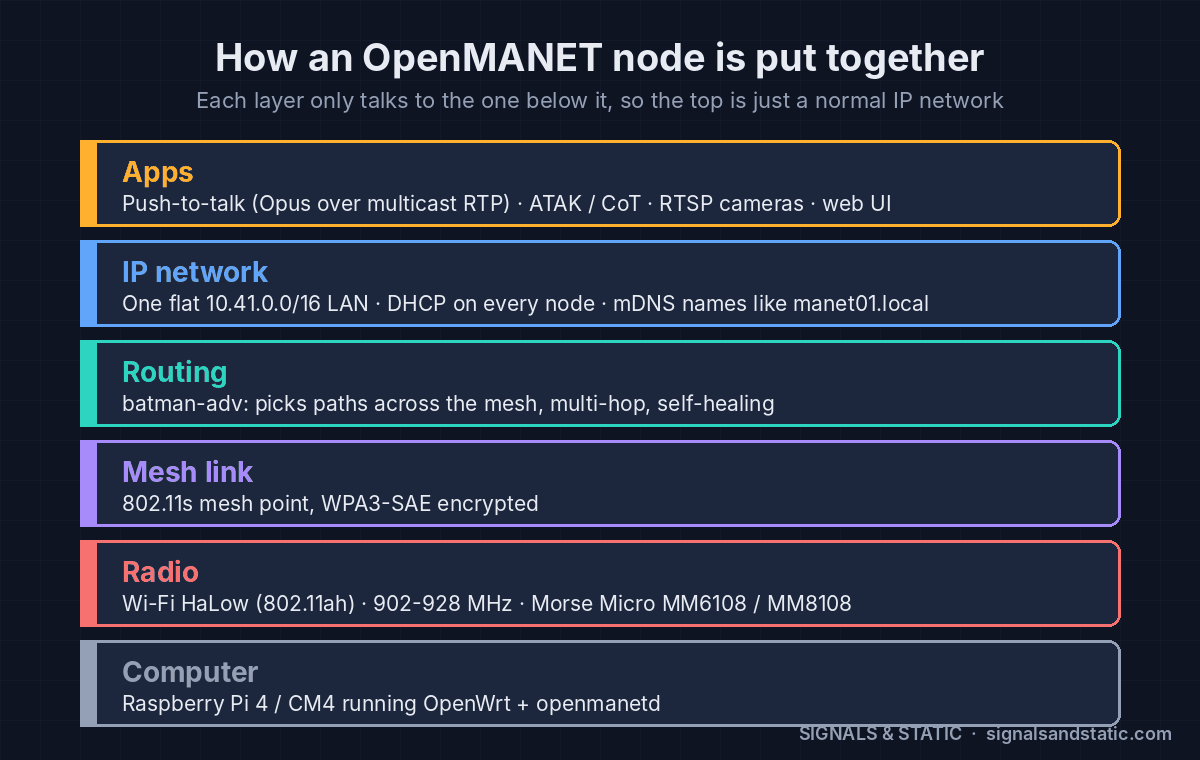
OpenMANET is an open-source mesh radio built from a Raspberry Pi and a Wi-Fi HaLow card. It is not a narrowband digital voice system like DMR. It’s a real IP network that happens to run over radio and builds itself.

  • The radio: Wi-Fi HaLow (802.11ah) in the 902–928 MHz band, using Morse Micro chips: the MM6108 (Seeed’s Wio-WM6108 card) or the newer MM8108 (Gateworks cards).
  • The computer: a Raspberry Pi 4 or a Compute Module 4 running OpenWrt, plus a daemon called openmanetd that handles the web UI, GPS, range testing and push-to-talk.
  • The mesh: 802.11s mesh links with batman-adv routing on top, so traffic hops node to node and finds a new path if one drops out.
  • The network: one flat 10.41.0.0/16 LAN. Every node runs its own DHCP server, so phones and laptops still get an address even if their node gets cut off from the rest. Names like manet01.local work across hops.
  • The way out: one node can be the “mesh gate,” which NATs the whole mesh onto Starlink, cellular or whatever uplink you have.

Your phone or laptop connects to a node over Ethernet or the node’s own 2.4/5 GHz access point, and from there it’s just… a network. Anything that speaks IP works.

OpenMANET node stack diagram: Raspberry Pi with OpenWrt, Wi-Fi HaLow radio, 802.11s mesh link, batman-adv routing, flat 10.41.0.0/16 IP network, and apps like push-to-talk, ATAK and RTSP

How an OpenMANET node stacks up, from the Pi and HaLow radio to the apps on top.

OpenMANET vs. Meshtastic

If you’ve played with Meshtastic or MeshCore, the easy way to think about OpenMANET is “same idea, a lot more pipe.” LoRa moves text messages and positions. HaLow moves real data: roughly 1 to 15 Mbps depending on the radio, channel width and your country’s rules. That’s enough for:

  • Push-to-talk voice (Opus audio over multicast, organized into talk groups)
  • ATAK integration, so everyone’s position and markers show up on the map
  • RTSP camera streams placed right on that map
  • ADS-B to Cursor-on-Target, and a way to join two separate meshes over the internet

The cost is power and money. A Pi plus a HaLow card pulls watts, not milliwatts, and a node runs a lot more than a $25 LoRa board. For what I want to do, that’s a fair trade.

The ham’s question: what is 27 dBm in watts?

The OpenMANET docs mention a tuned radio configuration file that pushes the Seeed card from about 21 dBm to about 27 dBm. I live in the HF/VHF/UHF world, where we talk in watts, so I had to translate.

dBm is decibels referenced to 1 milliwatt. Two rules get you everywhere: +3 dB doubles the power, and +10 dB is ten times the power.

dBm Power For reference
20 100 mW
27 0.5 W OpenMANET’s tuned HaLow card
30 1 W Part 15 conducted limit, 902–928 MHz
36 4 W EIRP Part 15 ceiling including antenna gain
37 5 W A typical handheld
47 50 W A typical mobile rig
50 100 W A typical HF rig
dBm to watts chart: 27 dBm is 0.5 W for the OpenMANET HaLow card, compared with the Part 15 limits and typical handheld, mobile and HF rig power

27 dBm is about half a watt. +3 dB doubles power, +10 dB is ten times.

So the whole thing runs on about half a watt. That sounds puny next to a 50 W mobile, but HaLow gets its range from narrow channels and how 900 MHz propagates, not from raw power. Same as on VHF/UHF: antenna height and a decent antenna will buy more than squeezing out a few more dB.

No license needed (and why I’m keeping it that way)

902–928 MHz is an unlicensed Part 15 band. For digitally modulated systems like HaLow, the limit is 1 W conducted with up to 6 dBi of antenna gain, which works out to a 4 W EIRP ceiling. Use a bigger antenna and you have to turn the power down to stay under it. Half a watt into a 2 dBi whip is about 0.8 W EIRP, well inside the line.

The catch is certification. The HaLow modules are certified with specific power settings and antennas, so a config file that raises power can push you outside the grant even while you’re under the absolute limit. And no, having a ham ticket doesn’t change that. I do have one, but I specifically want this project to work for people who don’t, so testing stays inside certified power and antenna combinations.

Why I’m building one

A stock OpenMANET node is already cool. But I keep thinking about where I’d take it:

  • A second, faster band (5 GHz) that kicks in when nodes are close together
  • A 5G mesh gate using the Quectel RM520N-GL modem already sitting on my bench
  • A custom CM4 carrier board instead of a stack of HATs and dongles
  • A 3D-printed, admittedly tacticool handheld to put it all in
  • A port for the drone detection project I’m working on, so its bearings land on everyone’s ATAK map

The one rule I’m setting for myself from day one: whatever I build has to be able to join anyone else’s stock OpenMANET mesh. Extras sit on top; I don’t fork the core. More on that plan in the next post.

Links if you want to go down the same hole

—
TL;DR: OpenMANET is a Raspberry Pi mesh radio over 915 MHz Wi-Fi HaLow that carries real IP traffic (voice, video, ATAK) on about half a watt, no license required. I’m building two nodes and then making it my own.